Rev. 000
TX 413 Service Manual
7-27
HYDRAULIC LIFT ASSEMBLY
8. Units, with serial numbers 240000100 through
240000200 will have a clamp and hoses routed
as shown in Fig. 282.
Figure 282 DSC-1072
Units, with serial numbers 240000201 and higher
will have a clamp and hoses routed as shown in
Fig. 283.
Figure 283 DSC-1073
7. Connect the next hydraulic hose to the hydraulic
fitting on the lift valve and tighten (Fig. 281).
Figure 281 DSC-1025
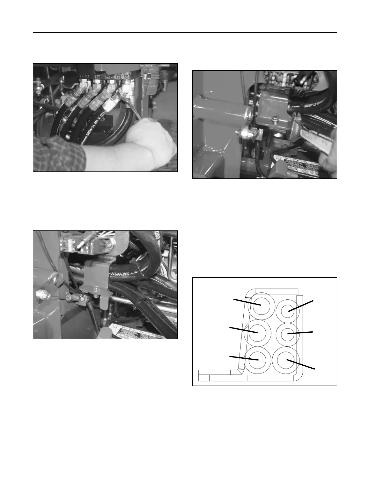
Proper hose placement through the clamp (Fig.
284).
A. Auxiliary Hose (female coupler)
B. Auxiliary Hose (male coupler)
C. Lift Cylinder Hose (ram end)
D. Tilt Cylinder Hose (ram end)
E. Tilt Cylinder Hose (barrel end)
F. Lift Cylinder Hose (barrel end)
Figure 284 105-9000 clamp
Front
Rear
A
B
C
D
E
F