Rev. 000
TX 413 Service Manual
7-47
HYDRAULIC LIFT ASSEMBLY
Joystick Assembly Removal
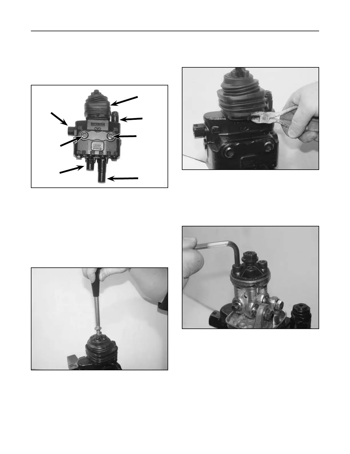
1. Remove handle (Fig. 353).
Figure 353 DSC-1436
2. Remove the 3 hex head screws and spring lock
washers, and remove the articulated holder (Fig.
355).
Figure 355 DSC-1382
Loader Valve Disassembly and Assembly
1. Before disassembly of any hydraulic component,
use a clean, dirt-free work surface and clean
solvent to prevent system contamination (Fig.
352).
Figure 352 DSC-1377
B
A
C
1. Remove tie cable around the rubber bellows and
remove the joystick assembly (Fig. 354). Wipe
excess grease from the joystick.
Figure 354 DSC-1381
A. Power beyond valve D. Rubber Bellows
B. Work port relief E. System relief
C. Spring Cap F. Detent spring cap
B
D
E
F