Rev. 000
TX 413 Service Manual
7-59
HYDRAULIC LIFT ASSEMBLY
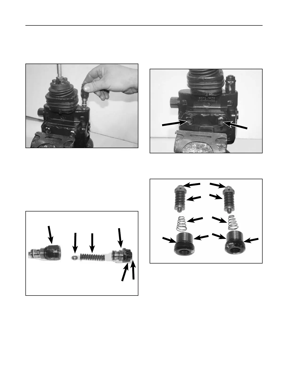
Work Port Relief
The work relief ports relieve the fluid spikes when the
Lift and Tilt Cylinders are being actuated (Fig 401 and
Fig. 402). These ports are non-adjustable. Port relief
setting is 2030 psi (140 bar).
Figure 401 DSC-1440
Figure 402 DSC-1442
Main Relief Valve
Pressure relief is designed to prevent internal
fluid pressure from rising above a pre-determined
maximum pressure (Fig. 399).
Figure 399 DSC-1438
Figure 400 DSC-1439
The relief valve is used to adjust to the specified
system pressure (2650 psi or 182.71 bar) by
increasing or decreasing the load on the spring
against the disc. Loosen the lock nut turn screw
inward to increase the pressure or outward to
decrease the pressure (Fig. 400).
A. Seat D. Plug
B. Relief E. O-ring
C. Spring
A. Bonnet D. Body
B. Disc E. Set screw
C. Spring F. Set screw lock nut
A
BC
D
F
E
A
B
C
D
E
E