Rev. 000
TX 413 Service Manual
7-37
HYDRAULIC LIFT ASSEMBLY
18. Start the unit and remove the cylinder lock
assembly. Operate the loader valve up, down,
and tilt to help purge the system of any air. Check
for any oil leaks at the hydraulic hose connectors.
After running the hydraulics recheck the oil
reservoir; see the Maintenance Section, Checking
the Hydraulic Reservoir, page 3-4. Shut engine
off.
19. Install the belt cover and the rear cover.
Quick Attachment Assembly Removal
1. Start engine and tilt the cylinder to lower the
quick attachment assembly so it is laying flat on
the ground (Fig. 321).
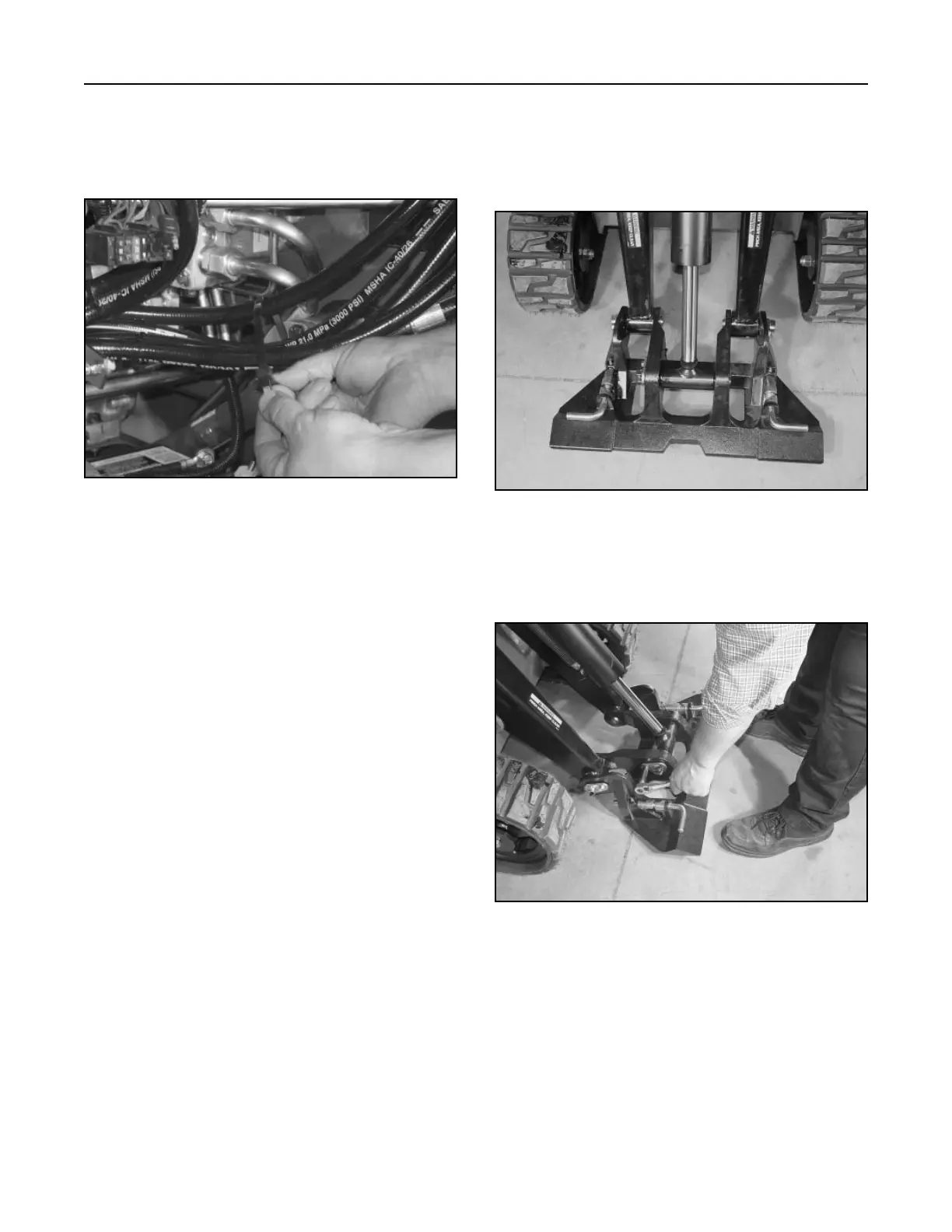
Figure 321 DSC-1076
17. Install a cable tie around the four hydraulic hoses
that go to the hydraulic lift valve. The cable tie
should be approximately 8" (20.3cm) away from
the hose clamp (Fig. 320).
Figure 320 DSC-1075
2. Remove the shoulder bolt retaining the pivot pin
for the ram end of the tilt cylinder (Fig. 322).
Figure 322 DSC-1077