Rev. 000
TX 413 Service Manual
7-9
HYDRAULIC LIFT ASSEMBLY
9. (Fig. 213, Ref. 4) Remove the upper hydraulic
hose from the fitting on the auxiliary valve on
units with serial numbers 240000200 and lower.
Figure 213 DSC-0951
8. Remove the two retaining bolts and nuts holding
the auxiliary valve to the frame and lower the
valve (Fig. 212).
Auxiliary Valve Installation
Note: As a reminder, prior to connecting the
hydraulic lines, the O-rings should be
replaced with new ones and lightly
lubricated with petroleum jelly.
1. Serial number range from 240000100 through
240000200, (Fig. 214, Ref. 4) Install the upper
hydraulic hose to the fitting on the auxiliary valve.
Figure 212 DSC-0948
10. For information on repairing the auxiliary valve,
refer to the Auxiliary Valve Service section of this
manual, page 7-60.
Figure 214 DSC-0951
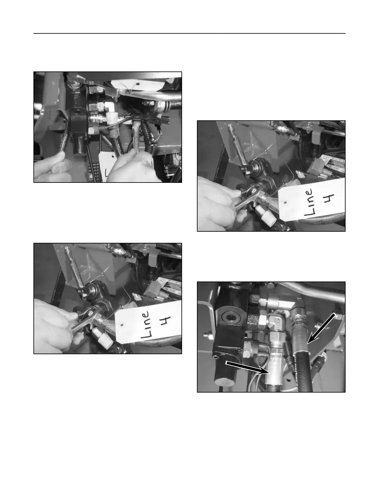
Serial number range from 240000201 and higher,
(Fig. 215) Lines 1 and 4 can be installed when
the valve is installed.
Figure 215 DSC-1039
Line
1
Line
4