Rev. 000
HYDRAULIC LIFT ASSEMBLY
7-8
TX 413 Service Manual
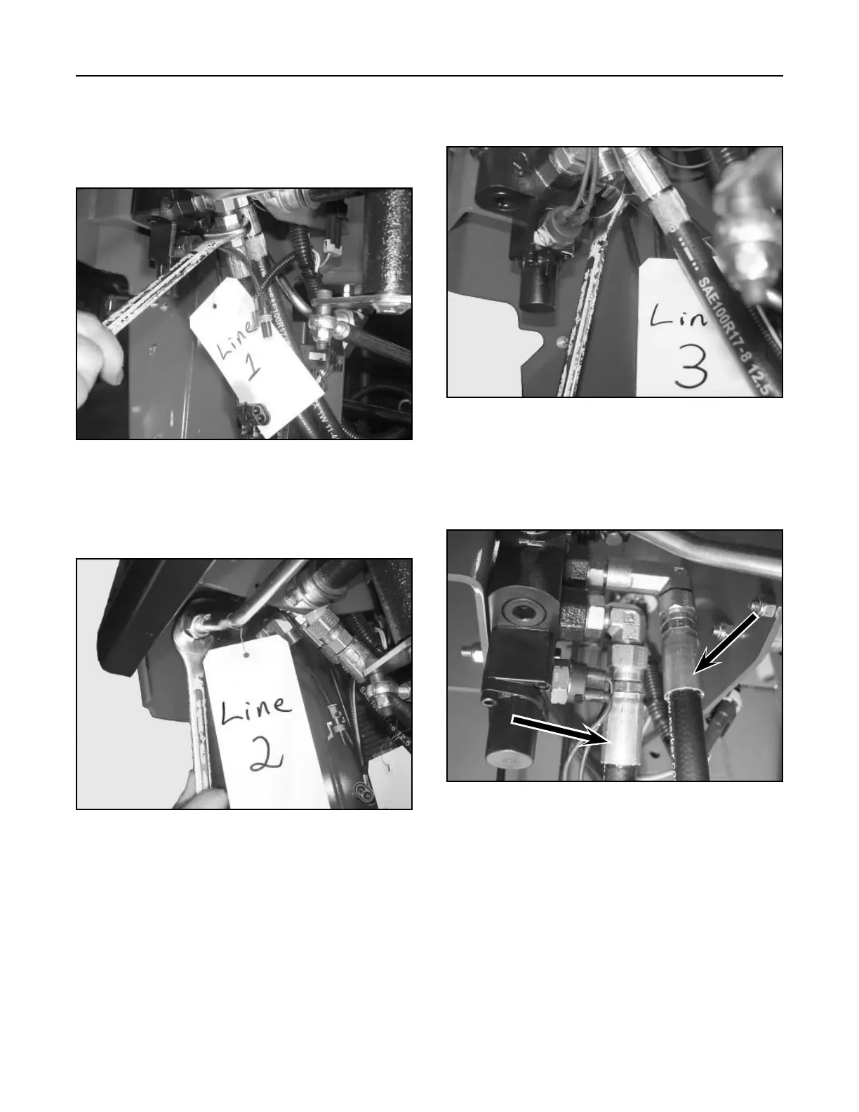
7. (Fig. 210, Ref. 3) Remove the hydraulic return
line from the front of the auxiliary valve.
Figure 210 DSC-0946
5. (Fig. 208, Ref. 1) Remove the rear hydraulic hose
from the fitting on the auxiliary valve
Note: It will be helpful to tag the hydraulic hoses
to ease reassembly.
Figure 208 DSC-0944
6. (Fig. 209, Ref. 2) Remove the hydraulic line
coming from the loader arm valve.
Figure 209 DSC-0945
Note: Lines 1 and 4 can be removed prior to
removing the valve retaining bolts on units
with serial numbers 240000201 and higher
(Fig. 211).
Figure 211 DSC-1039
Line
1
Line
4