Rev. 000
TX 413 Service Manual
8-27
DRIVE SYSTEM
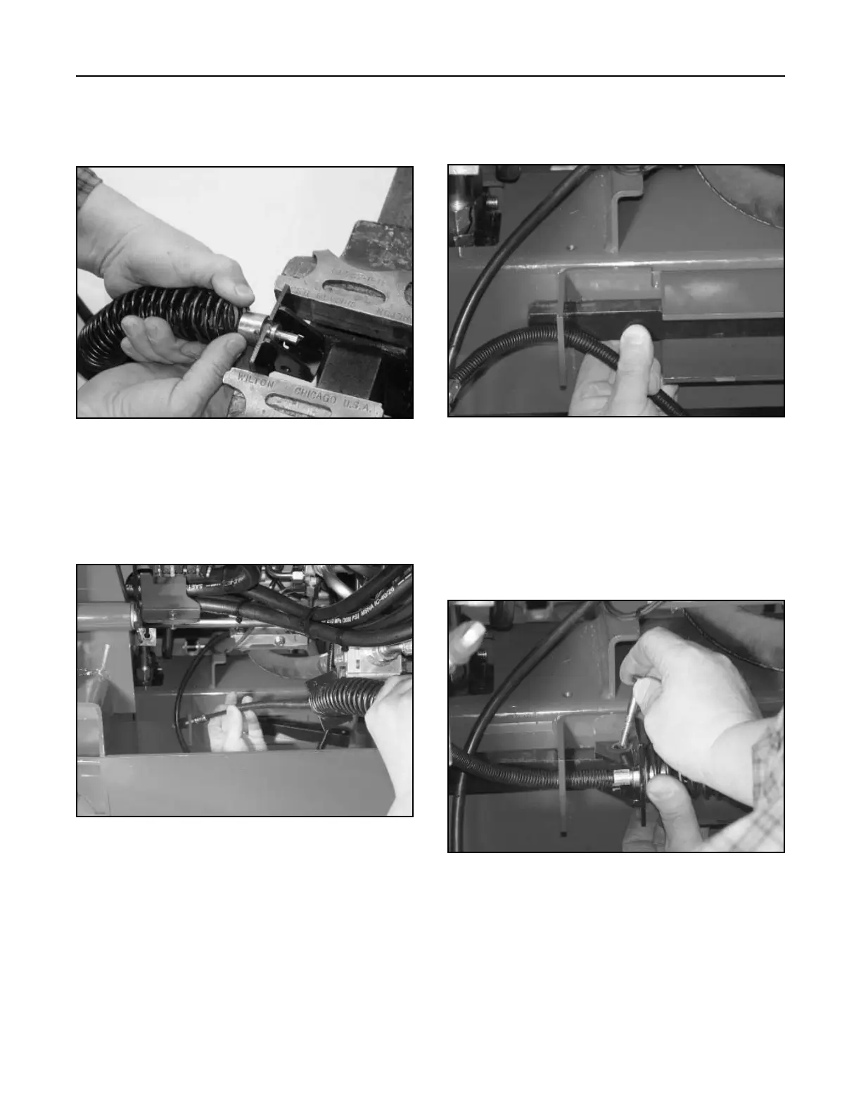
14. Remove the end of the rope, by cutting it. Slide
the brake springs back and install the tube guide
and tighten the set screw (Fig. 514).
2. Slide the brake bar through the bracket on the
frame, with the brake cable pulled to the front of
the bracket (Fig. 516).
Figure 514 DSC-1285
Figure 516 DSC-1287
Brake Assembly Installation
1. Slide the brake cable through the bracket on the
frame (Fig. 515).
Figure 515 DSC-1286
Note: Serial #200000201 and higher will have
an extra hole drilled to hold brake “OFF”
manually.
3. Install bolt and nut through the cable bracket and
the brake bar, left side (Fig. 517).
Figure 517 DSC-1288