Rev. 000
TX 413 Service Manual
6-9
HYDRAULIC SYSTEM
Figure 115 DSC-0876
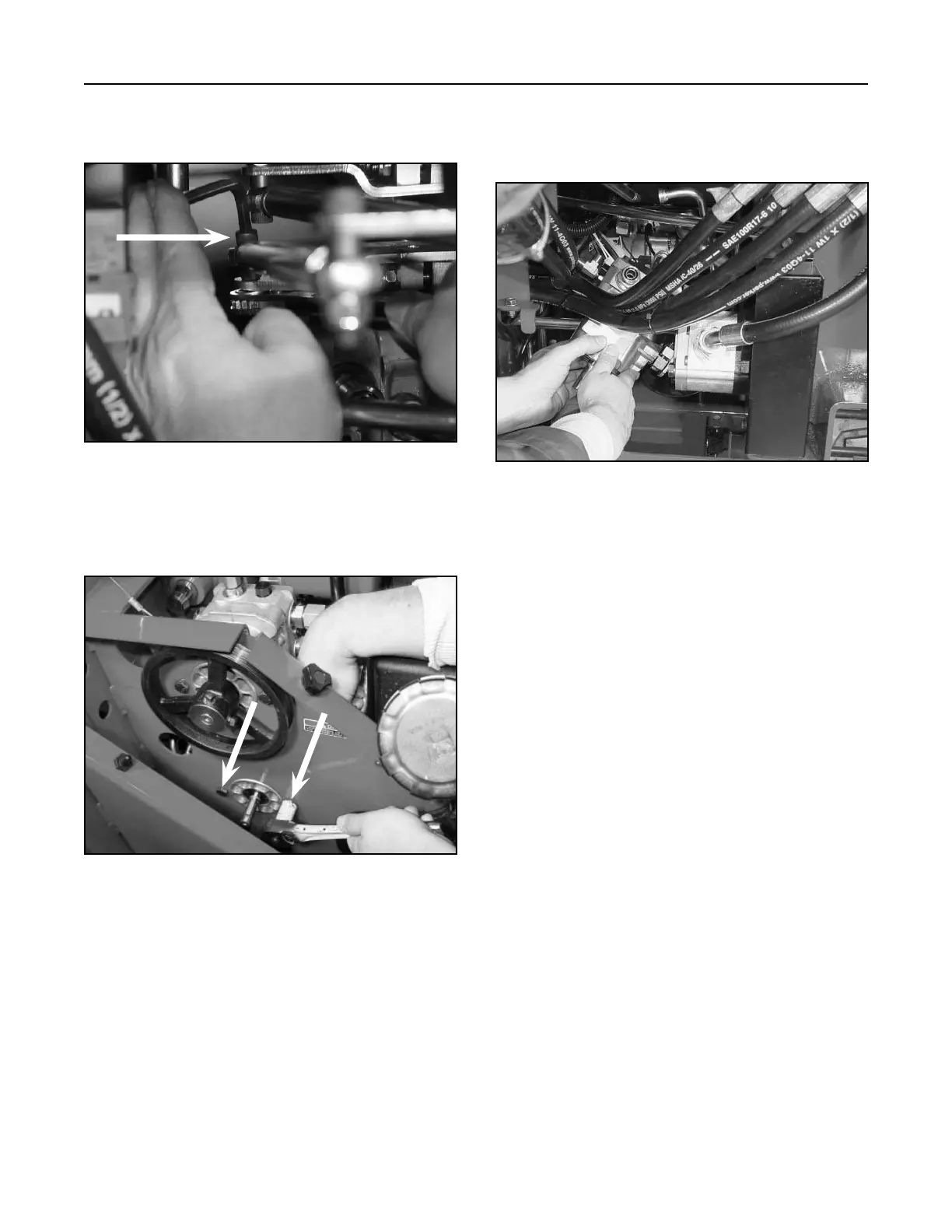
14. Remove the Allen bolt, spacer, and nut from the
pump lever assembly (Fig. 115).
15. Remove the two bolts and nuts holding the
hydrostatic pump to the frame (Fig. 116).
Figure 116 DSC-0877
16. Carefully lower the hydrostatic pump down and
maneuver under the hydraulic hoses and out of
the backside of the unit (Fig. 117).
Figure 117 DSC-0878
Hydrostatic Pump (Right Drive)
Installation
Note: As a reminder, prior to connecting the
hydraulic lines, the O-rings should be
replaced with new ones and lightly
lubricated with petroleum jelly.
1. When installing a new hydrostatic pump, make
sure all the hydraulic fittings are installed
properly; refer to the Hydrostatic Pump (Right
Drive) Fittings and Pump Lever Assembly on
pages 6-17.
Hydrostatic Pump Service
For hydrostatic pump service, refer to Hydro-Gear
BDP-10 service manual (Toro P/N 492-4789).