Rev. 000
Figure 118 DSC-0884
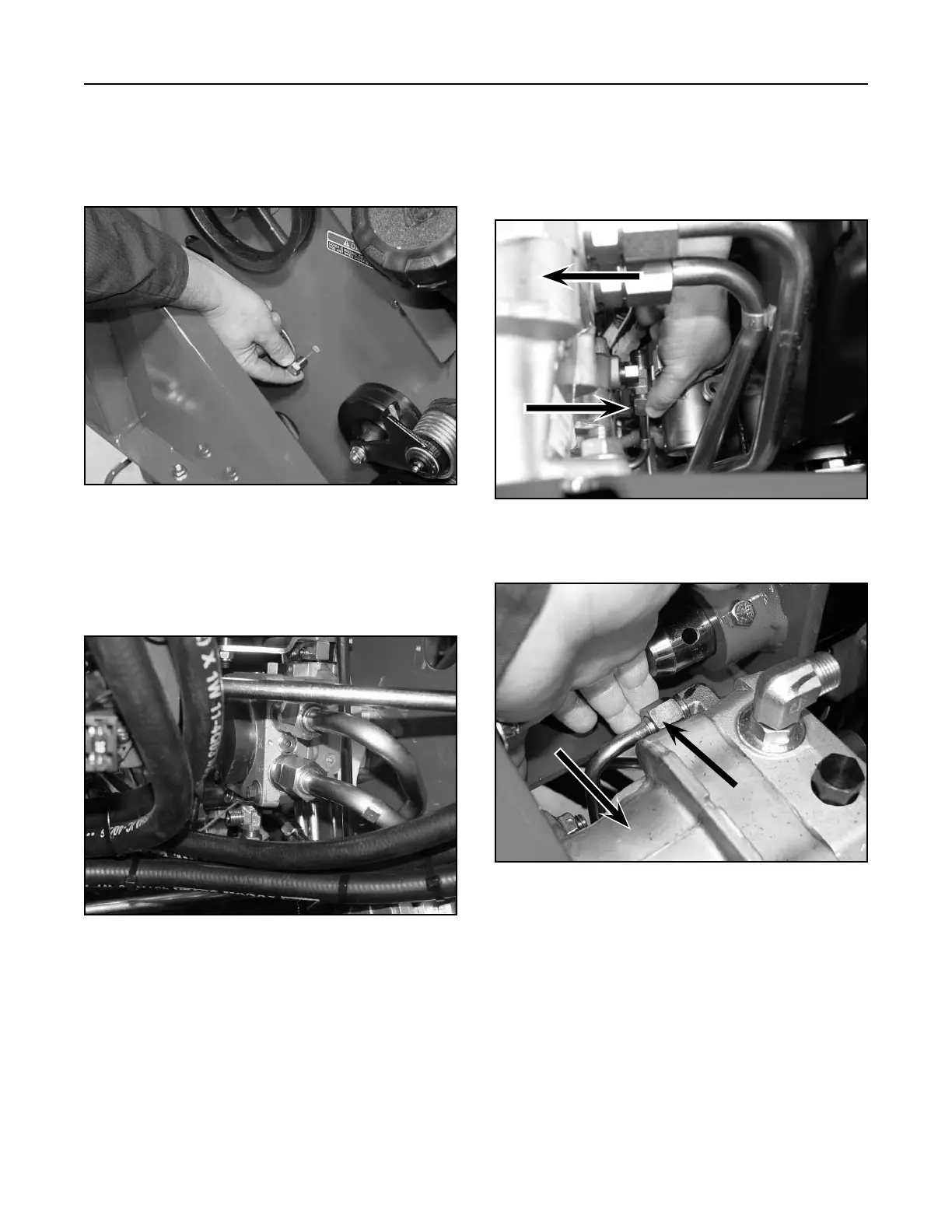
3. Connect the two hydraulic lines that run to the
right wheel motor, (page 6-2, Ref. 3A and 3B),
and hand tighten (Fig. 119).
Figure 119 DSC-0871
2. Maneuver the right drive hydrostatic pump under
the hydraulic hoses and up to the opening in the
frame. Secure the frame with two bolts and nuts.
DO NOT tighten the bolts at this time (Fig. 118).
HYDRAULIC SYSTEM
6-10
TX 413 Service Manual
4. Connect and hand tighten the inlet hydraulic line
from the T-fitting adapter (page 6-2, Ref. 7) from
the right drive hydrostatic pump to the left drive
hydrostatic pump (Fig. 120, top view and Fig
121).
Figure 120 DSC-0885
Figure 121 DSC-0886
A
A. Left Hand Drive Pump
A. Left Hand Drive Pump
B. Inlet Hydraulic Line from T-fitting Adapter
A
B