Rev. 000
TX 413 Service Manual
6-11
HYDRAULIC SYSTEM
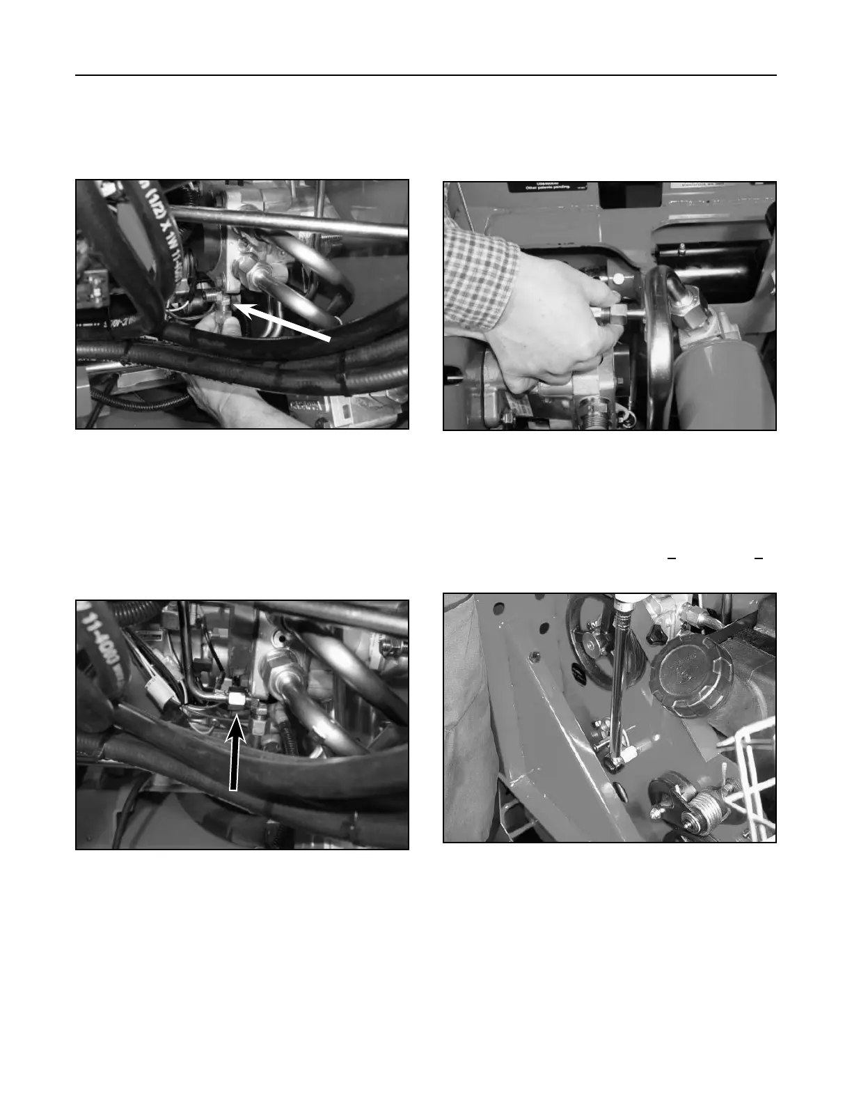
5. Connect and hand tighten the case drain
hydraulic line (page 6-2, Ref. 2) to the bottom of
the T-fitting adapter, located on the bottom of the
right drive hydrostatic pump (Fig. 122, rear view).
Figure 122 DSC-0887
6. Connect and hand tighten the case drain
hydraulic line (page 6-2, Ref. 5) from the T-fitting
located at the bottom of the right drive hydrostatic
pump to the top 90° fitting located on the top of
left drive hydrostatic pump (Fig. 123, rear view).
Figure 123 DSC-0869
Figure 125 DSC-0888
8. Recheck all the fitting connections and tighten.
9. Tighten the two right drive hydrostatic pump
mounting bolts and torque to 50 + 5 ft-lbs. (70 + 7
Nm) (Fig. 125).
7. Connect and hand tighten the case drain
hydraulic line (page 6-2, Ref. 6), to the 90° fitting
located on the top of the left drive hydrostatic
pump (page 6-2, Ref. 1) (Fig. 124).
Figure 124 DSC-0903