ATTACHMENTS
10-12 TX 413 Service Manual
Rev. 001
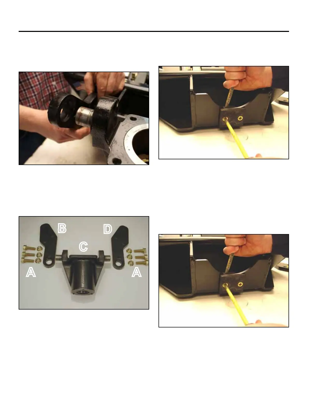
4. While supporting the auger housing, remove the
pivot plate on one side from the frame assembly.
The auger housing can now be set aside (Fig. 038).
Fig 038 PICT-8710
Fig 040 CLR DSC-0155
6. Remove the stop pad from the frame assembly (Fig.
040).
5. Now remove the three pivot plate bolts from the
other side and remove the pivot plate (Fig. 039).
A. Nuts and bolts C. Auger housing
B. RH pivot plate D. LH pivot plate
Fig 039 CLR DSC-0174
Fig 041 CLR DSC-0155
1. Install the stop pad on the frame assembly (Fig.
041).
Reassemble Power Head into Frame
Assembly
A A
B
C
D