Rev. 000
HYDRAULIC LIFT ASSEMBLY
7-50
TX 413 Service Manual
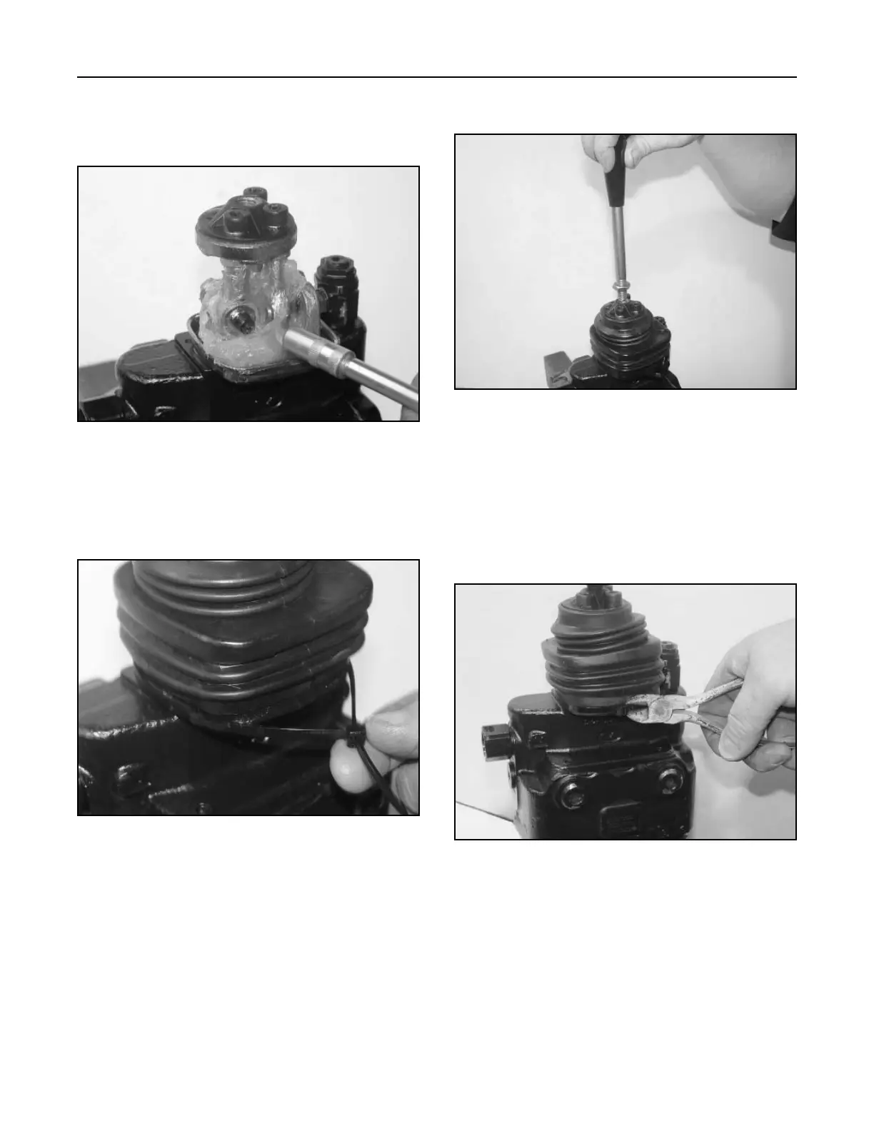
7. Install the lift/tilt handle (Fig. 366).
Figure 366 DSC-1436
6. Install the rubber bellows over the base plate and
install the tie strap in the groove of the rubber
bellows (Fig. 365).
Figure 365 DSC-1435
Spool Removal
Note: To disassemble and assemble the valve, it
is best to hold the valve in a bench vise.
1. Remove tie cable around the rubber bellows and
remove (Fig. 367).
Figure 367 DSC-1381
5. Lubricate all of the articulated parts inside the
mechanical joystick area with synthetic base
grease grade NLGI2 (Fig. 364).
Figure 364 DSC-1434