Rev. 000
Figure 161 DSC-1461
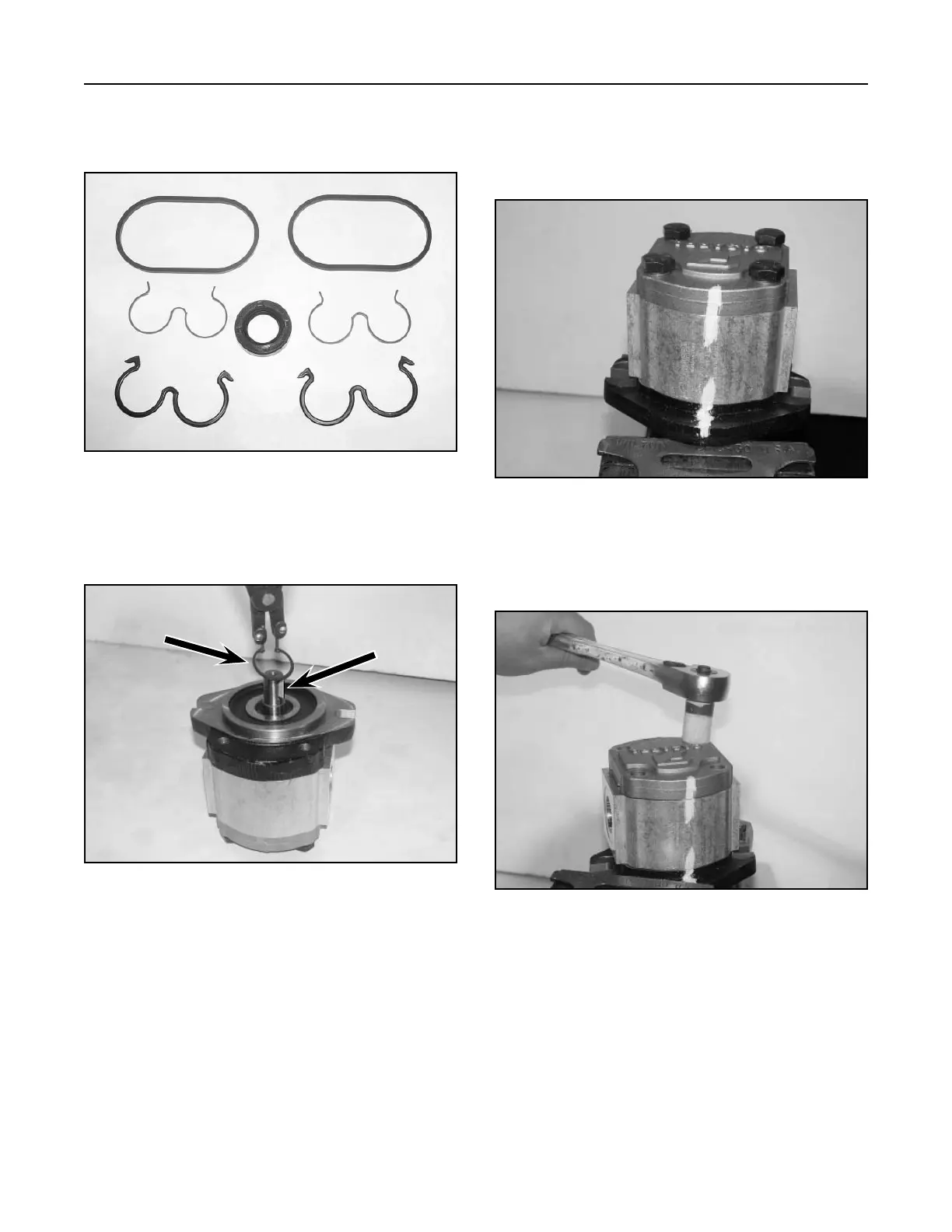
1. Seal Kit for gear pump assembly (Fig. 161).
Gear Pump Disassembly
HYDRAULIC SYSTEM
6-22
TX 413 Service Manual
2. Remove the snap ring and woodruff key from the
input shaft (Fig. 162).
Figure 162 DSC-1471 with key
B
A
A. Snap ring B. Woodruff key
4. Remove the four retaining bolts and washers
(Fig. 164).
Figure 164 DSC-1463
3. Mark the outside gear pump, body, front cover,
and rear cover, to make sure they assemble
together the same way they were disassembled
(Fig. 163).
Figure 163 DSC-1462