Rev. 000
HYDRAULIC LIFT ASSEMBLY
7-10
TX 413 Service Manual
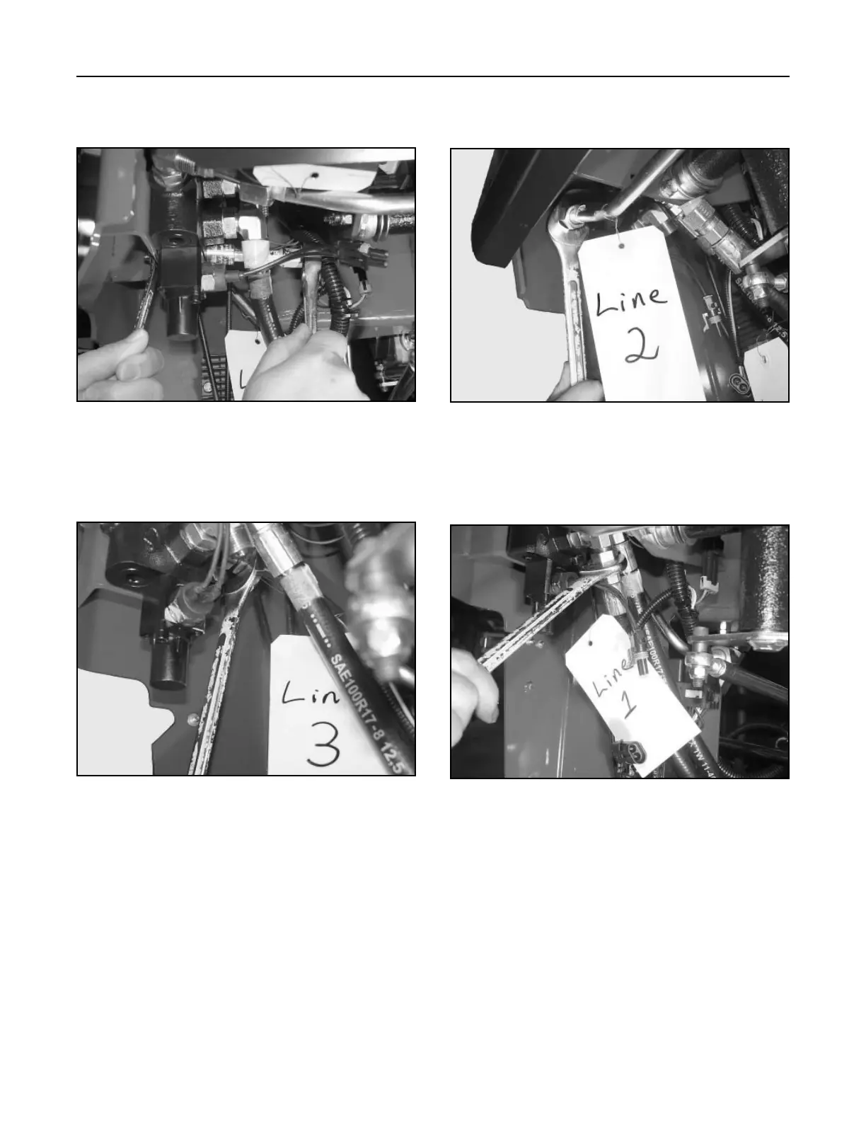
4. (Fig. 218, Ref. 2) Install the hydraulic line from
the loader valve to the auxiliary valve.
Figure 218 DSC-0945
5. (Fig. 219, Ref. 1) Install the lower hydraulic hose
to the fitting on the auxiliary valve.
Figure 219 DSC-0944
2. Install the two retaining bolts and nuts holding the
auxiliary valve to the frame (Fig. 216).
Figure 216 DSC-0948
3. (Fig. 217, Ref. 3) Install the hydraulic return line
to the auxiliary valve.
Figure 217 DSC-0946