Rev. 000
TX 413 Service Manual
7-11
HYDRAULIC LIFT ASSEMBLY
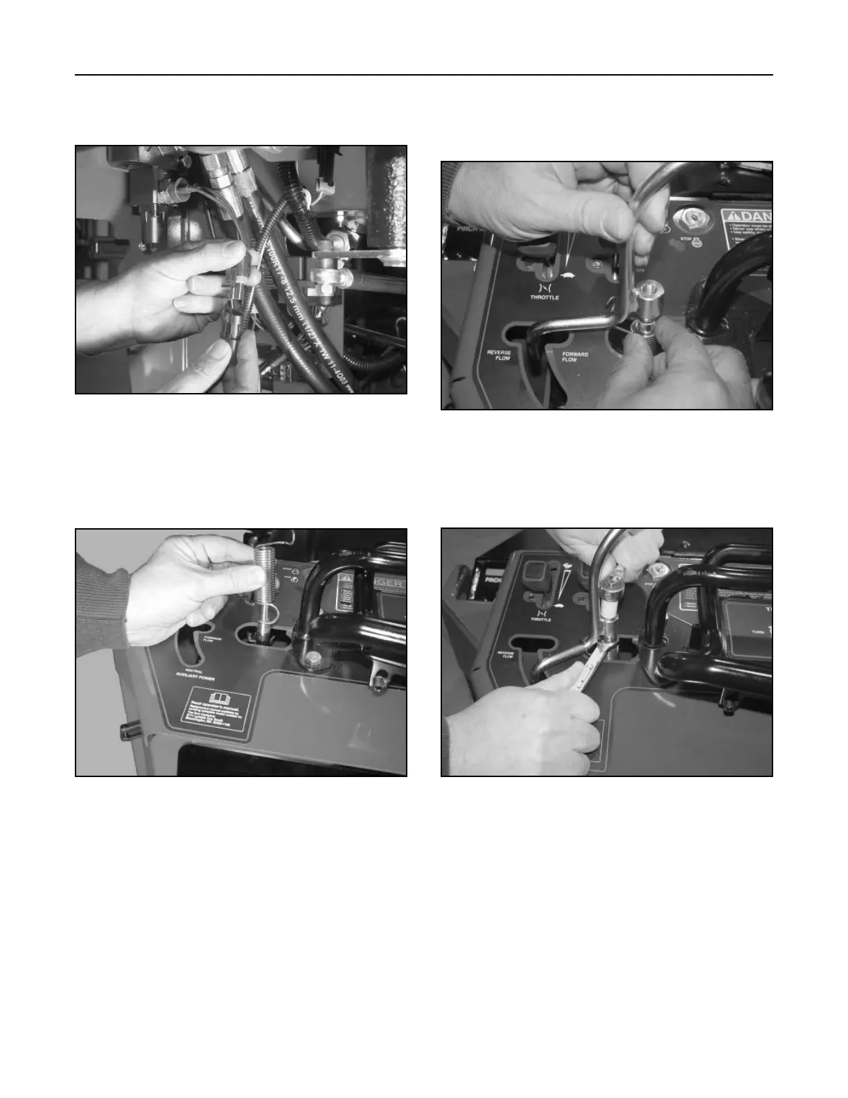
6. Connect the neutral ball switch at the harness
connector (Fig. 220).
Figure 220 DSC-0942
7. Slide the torsion spring over the control shaft,
with the large hook end of the spring facing down
(Fig. 221).
Figure 221 DSC-0954
10. Start the unit and check the hydraulic fittings for
any leaks. Install a hydraulic attachment and
operate the auxiliary valve in both the forward
and reverse flow to purge any air out of the
system. Also, operate the loader arm valve up,
down, and tilt to help purge the system of any air.
Recheck for leaks.
11. Install the rear cover.
8. Turn the torsion spring clockwise and hold. Slide
the auxiliary lever over the control shaft and hook
the spring end over the auxiliary lever (Fig. 222).
Figure 222 DSC-0941
9. Install the washer and retention nut on the top of
the lever and tighten the nut (Fig. 223).
Figure 223 DSC-0939