Rev. 000
HYDRAULIC LIFT ASSEMBLY
7-36
TX 413 Service Manual
Note: Units with a serial number of 240000201
and higher have a revised hydraulic hose
clamp. It is easier to install this clamp by
using a crescent wrench to pry down on
the bracket to install the bolt and nut (Fig.
319).
Figure 319 DSC-1073
16. Before installing the clamp, route the hoses
through the clamp, refer to Fig. 317. Install the
hose clamp, located on the lower left corner.
Note: Units with a serial number of 240000001
through 240000200 will have the clamp
shown in Fig. 318.
Figure 318 DSC-1072
14. Install a cable tie around all four hydraulic hoses,
about 3" (7.6cm) from the rear hose clamp in the
loader arm assembly (Fig. 316).
Figure 316 DSC-1071
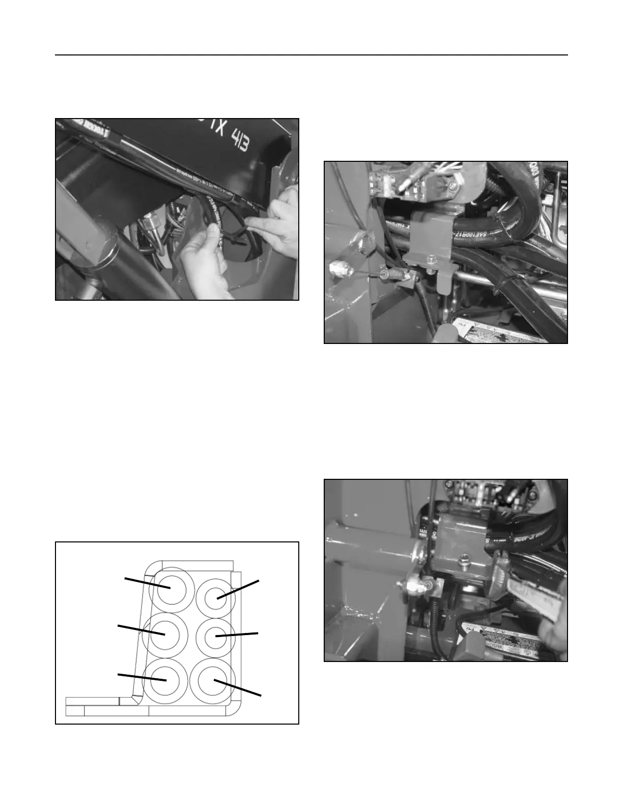
Proper hose placement through the clamp (Fig.
317).
A. Auxiliary Hose (female coupler)
B. Auxiliary Hose (male coupler)
C. Lift Cylinder Hose (ram end)
D. Tilt Cylinder Hose (ram end)
E. Tilt Cylinder Hose (barrel end)
F. Lift Cylinder Hose (barrel end)
Figure 317 105-9000 clamp
15. Start engine and raise the loader arm assembly
to the fully raised position. Remove locking arm
assembly from the hydraulic lift cylinder and
lower the loader arm assembly. Shut off engine.
Front
Rear
A
B
C
D
E
F