Rev. 000
TX 413 Service Manual
7-35
HYDRAULIC LIFT ASSEMBLY
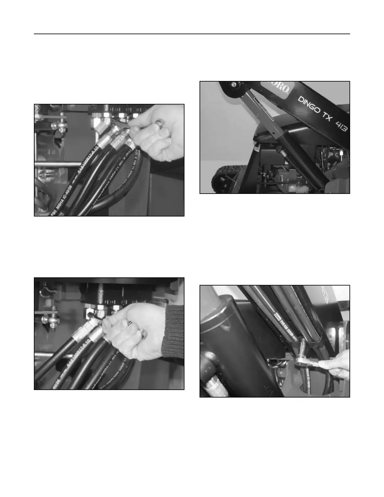
13. Install the two hose clamps, located under the
loader arm assembly (Fig. 315).
Note: Make sure the two auxiliary hydraulic
hoses are routed to the outside of the arm.
The wider portion of the hose clamp goes
over the auxiliary hydraulic hoses.
Figure 315 DSC-1042
Note: Prior to connecting the hydraulic lines,
the o-rings and seals should be replaced
with new ones and lightly lubricated with
petroleum jelly.
10. Connect hydraulic hose to the hydraulic lift valve
fitting and tighten (Fig. 312).
12. Start engine and raise the loader arm assembly
to the fully raised position. Install the cylinder lock
in the hydraulic lift cylinder and shut engine off
(Fig. 314).
Figure 312 DSC-1047
Figure 314 DSC-1041
11. Connect the next hydraulic hose (which should
be marked) to the hydraulic lift valve fitting and
tighten (Fig. 313).
Figure 313 DSC-1045