Rev. 000
HYDRAULIC LIFT ASSEMBLY
7-48
TX 413 Service Manual
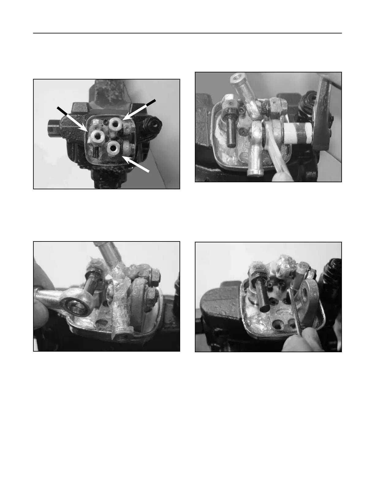
5. Remove the pivot for the lift and tilt operation.
Remove the nut holding the joystick joint (Fig.
358).
Figure 358 DSC-1395
4. Slide the end rod off the joystick pin of the
joystick joint for the Tilt Cylinder (Fig. 357).
6. Turn the loader lift joystick joint and remove two
hex head screws, then remove the joystick pivot
(Fig. 359).
Figure 357 DSC-1726
Figure 359 DSC-1728
3. Pictured below (Fig. 356) are the joystick joints:
A. Tilt Cylinder operation
B. Loader Lift Cylinder operation
C. Pivot for Lift and Tilt operation
Figure 356 DSC-1391
A
B
C