Rev. 000
TX 413 Service Manual
7-57
HYDRAULIC LIFT ASSEMBLY
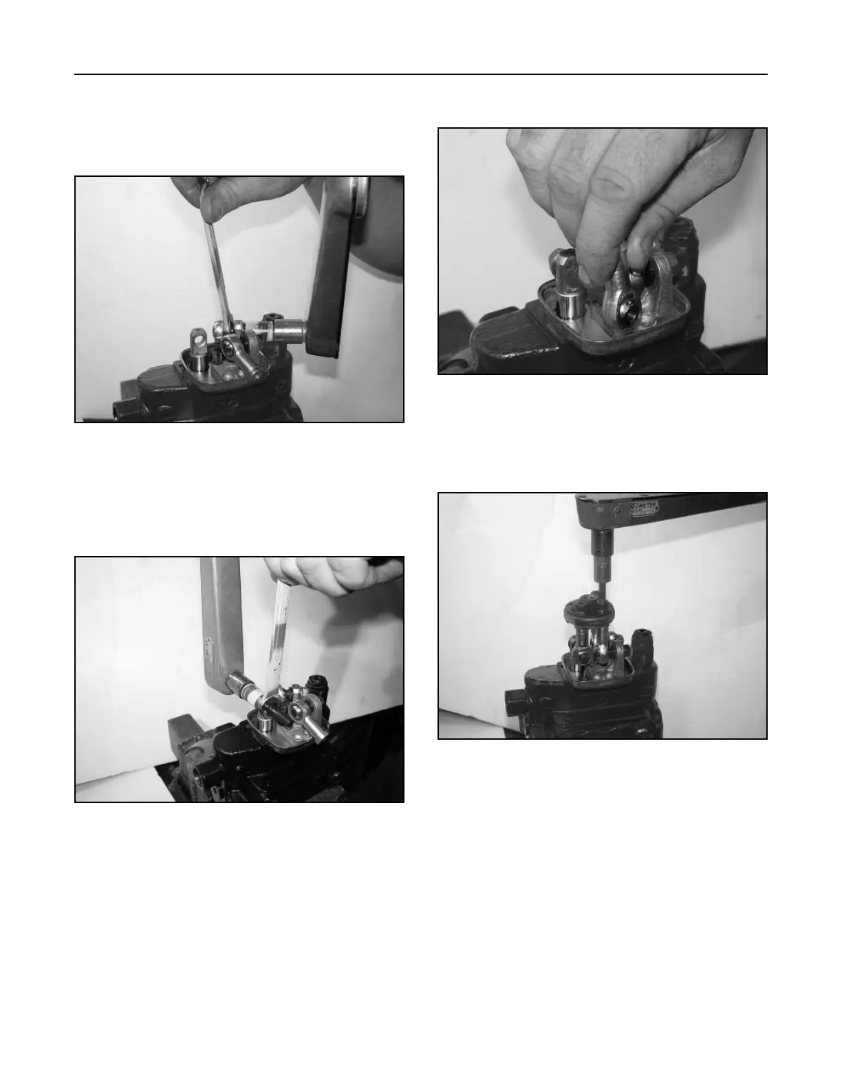
12. Install the end rod on the joystick pin (Fig. 393).
Figure 393 DSC-1430
13. Install the articulated holder with 3 cap screws
and torque to 18 ft-lbs. (24.4 Nm) (Fig. 394).
Figure 394 DSC-1431
10. Apply a medium strength threadlocking material
to the threads of the loader lift joystick joint, and
install the retaining nut to the lift spool. Torque
the nut to 31 ft-lbs. (42 Nm) (Fig. 391).
Figure 391 DSC-1428
11. Apply a medium strength threadlocking material
to the threads of the joystick pin and torque the
nut to 31 ft-lbs. (42 Nm) (Fig. 392).
Figure 392 DSC-1429