Rev. 000
HYDRAULIC LIFT ASSEMBLY
7-62
TX 413 Service Manual
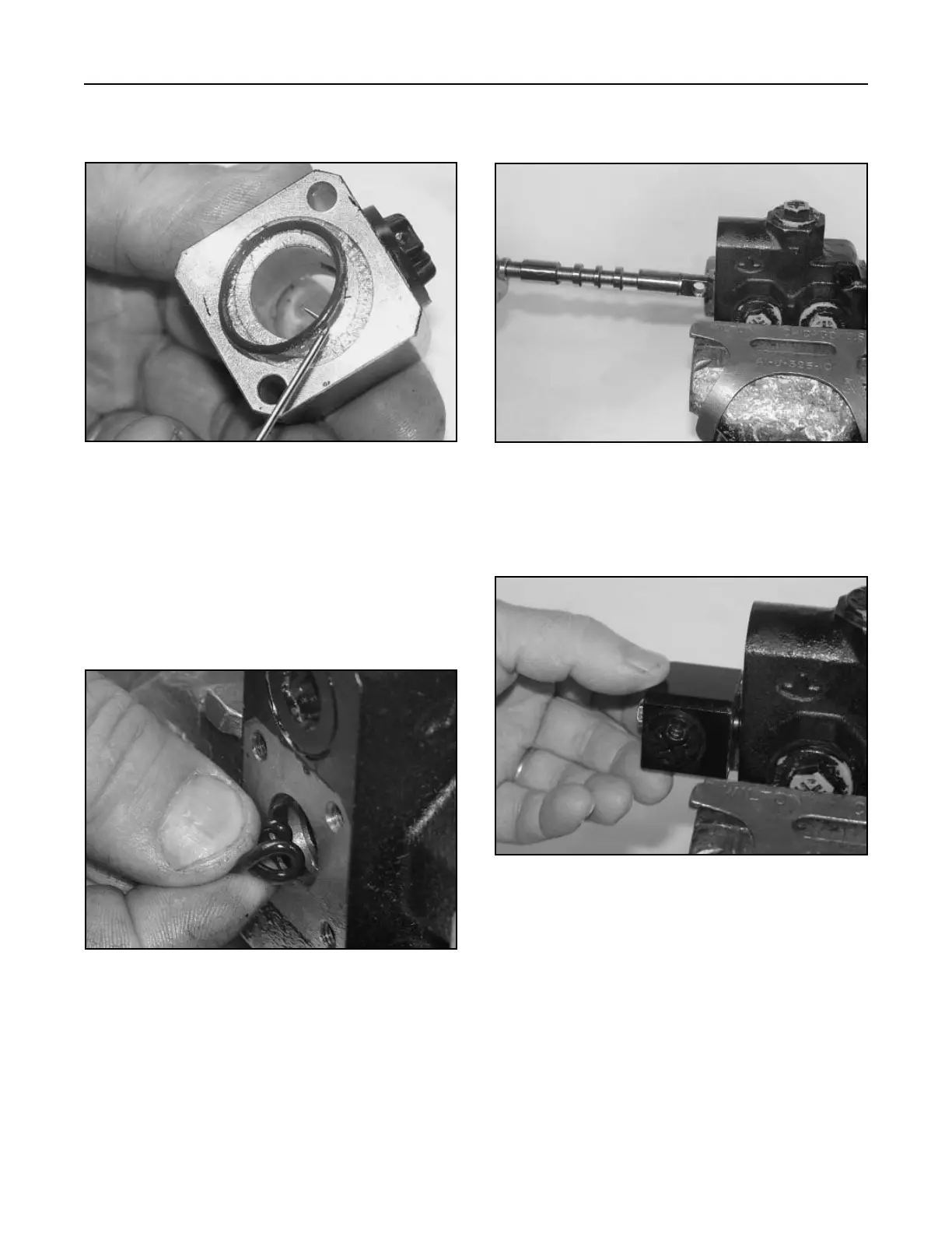
8. Remove the two o-rings located at each end of
the neutral switch block (Fig. 411).
2. Lubricate and carefully install the spool, from the
bottom of the valve (Fig. 413).
Figure 411 DSC-1453
Figure 413 DSC-1455
Assembly
Note: Replace all seals and o-rings with new
parts. Lubricate the valve, o-rings, and
spool with 10W-30 oil prior to installation.
1. Lubricate and install the two o-rings located at
the top and bottom of the valve (Fig. 412).
3. Install the neutral switch block with two hex head
screws, torque to 5 ft-lbs. (6.8 Nm) (Fig. 414).
Figure 412 DSC-1454
Figure 414 DSC-1456