DRIVE SYSTEM
8-10
TX 413 Service Manual
Rev. 000
Figure 451 DSC-0794
4. Align the closest notch in the tension screw to the
locking bolt hole and secure the screw with the
locking bolt and nut (Fig. 453).
Figure 453 DSC-0793
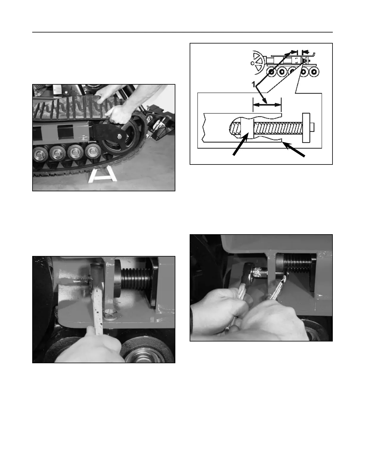
3. Turn the tensioning screw counter-clockwise,
(Fig. 451), until the distance between the tension
nut and the back of the tensioner arm is 2-1/2
inches (6.35cm) (Fig. 452).
Figure 452 track install #3
1. = 2-1/2 inches
(6.35cm)
A
B
A. Tension nut B. Tensioner Arm
Figure 450 DSC-0796
2. Push the track under and between the road
wheels. Starting at the bottom of the tension
wheel, install the track around the wheel by
rotating the track rearward while pushing the lugs
into the wheel (Fig. 450).
 Loading...


