Rev. 000
TX 413 Service Manual
8-19
DRIVE SYSTEM
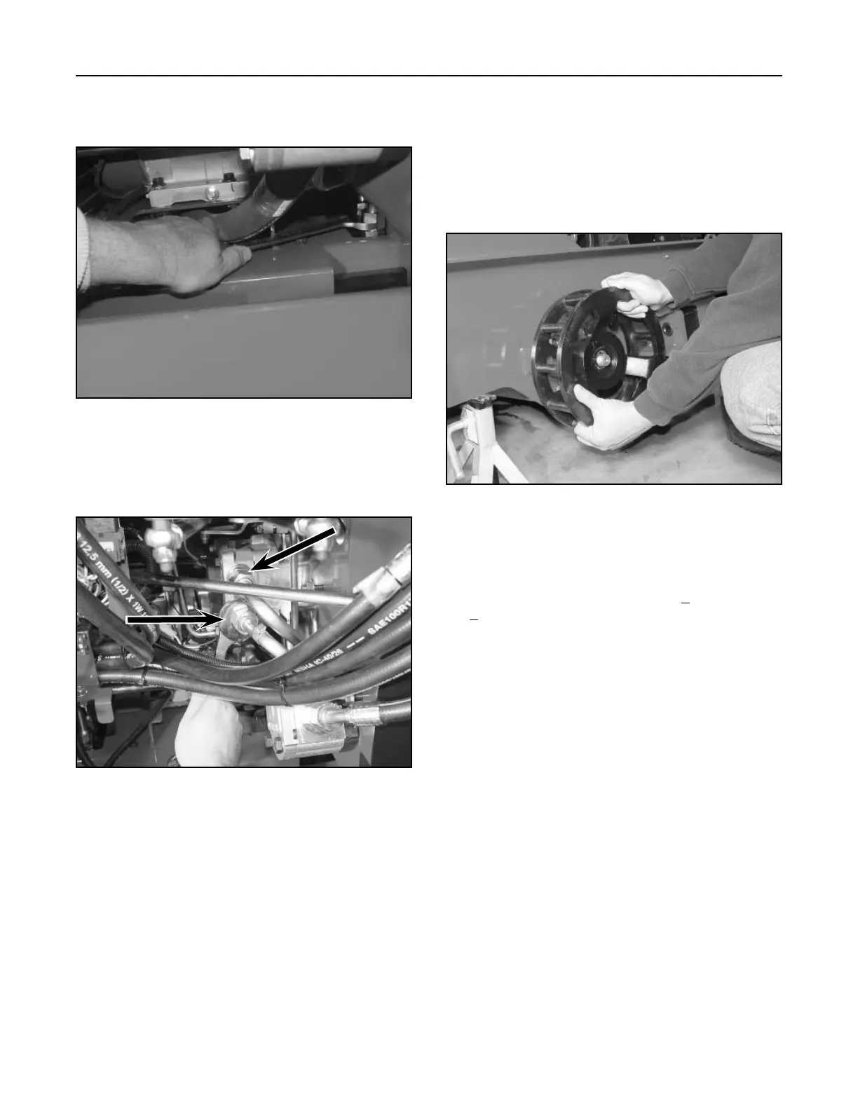
3. Install the hydraulic lines to the hydraulic fittings
on top of the wheel motors and tighten (Fig. 485).
Figure 485 DSC-0842
4. Tighten the hydraulic lines that connect to the
hydrostatic pumps (Fig. 486).
Figure 486 DSC-0845
5. Clean the motor shaft with a degreaser to make
sure there is no grease or dirt.
Note: Do not use grease or anti-seize compound
on the shaft.
Install the drive wheel on the shaft, aligning the
keyway (Fig. 487).
Figure 487 DSC-0849
6. Install the nut on the shaft. Lock the drive wheel
with a pry bar or similar tool installed in the
spokes and torque the nut to 300 + 50 ft-lbs. (407
+ 68 Nm).
Note: After achieving the specified torque, make
sure the hole in the motor shaft is aligned
with one of the slots on the castle nut to
install the cotter pin, DO NOT loosen the
nut to align the cotter pin hole.