Rev. 000
7. Recheck all of the fitting connections and tighten.
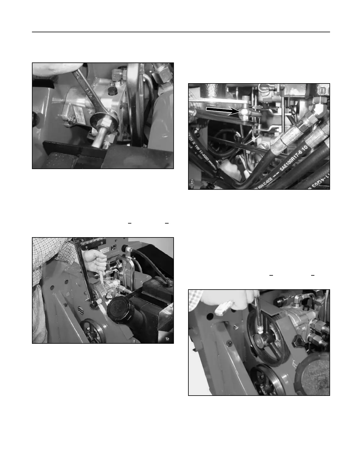
8. Tighten the two left drive hydrostatic pump
mounting bolts and torque to 50 + 5 ft-lbs. (70 +
7 Nm) (Fig. 141).
Figure 141 DSC-0907
6. Connect and tighten the top hydraulic line (page
6-2, Ref. 4A) to the wheel motor (Fig. 140).
Figure 140 DSC-0906
HYDRAULIC SYSTEM
6-16
TX 413 Service Manual
10. Apply anti-seize compound on the left drive
hydrostatic pump shaft. Also, apply a medium
strength threadlocking material to the pulley set
screws. Install the hydrostatic pulley (grooved-
pulley) on the shaft and key, making sure the set
screws are facing outward and the pulley is flush
with the end of the pump shaft (Fig. 143), then
tighten the set screws 215 + 35 in-lbs. (24 + 4
Nm).
Figure 143 DSC-0891
9. Position the control handle so you can install
the Allen head bolt through the rod end bearing,
spacer, pump lever assembly, and a nut. Tighten
the assembly and make sure the control handle
is moving freely (Fig. 142).
Figure 142 DSC-0896