TX 413 Service Manual
6-19
HYDRAULIC SYSTEM
Rev. 000
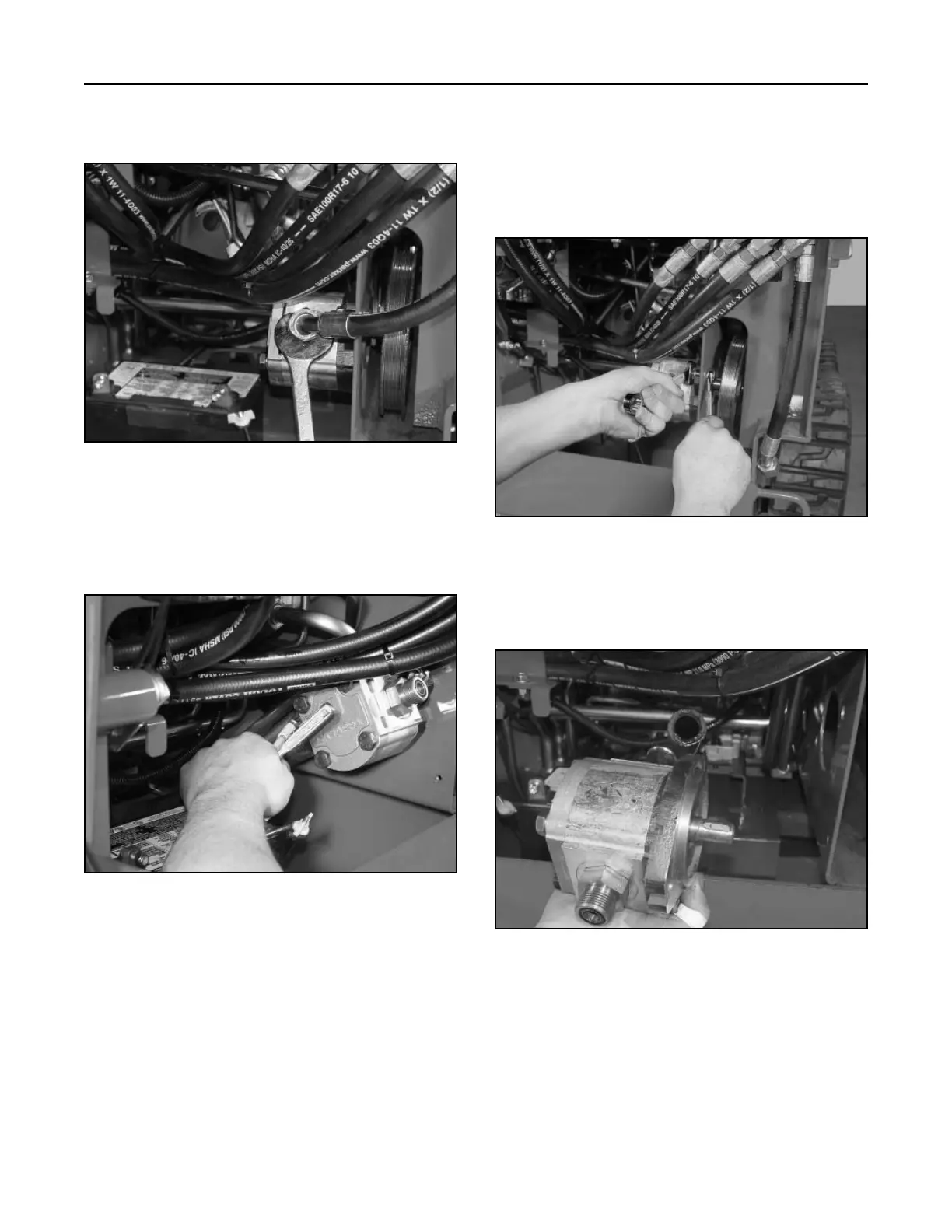
4. Disconnect and remove the hydraulic line going
to the loader arm valve (Fig. 150).
Figure 150 DSC-0911
5. Loosen the hose clamp and remove the hydraulic
suction hose from the front of the gear pump and
slide the hose off the fitting (Fig. 151).
Figure 151 DSC-0912
6. Loosen and remove the two mounting bolts and
nuts that retain the gear pump to the frame.
Once the pump mounting bolts are loosened and
removed, the pump can be pulled away from the
frame and the pulley can be removed from the
shaft (Fig. 152).
Figure 152 DSC-0913
7. Remove the gear pump from the frame (Fig.
153).
Figure 153 DSC-0916
8. For information on repairing the gear pump refer
to the Gear Pump Repair section on page 6-21.