EasyManuals Logo

Toro Dingo TX 413 User Manual

Toro Dingo TX 413
244 pages
To Next Page IconTo Next Page
To Previous Page IconTo Previous Page
Page #94 background imageLoading...
Page #94 background image
Rev. 000
TX 413 Service Manual
7-5
HYDRAULIC LIFT ASSEMBLY
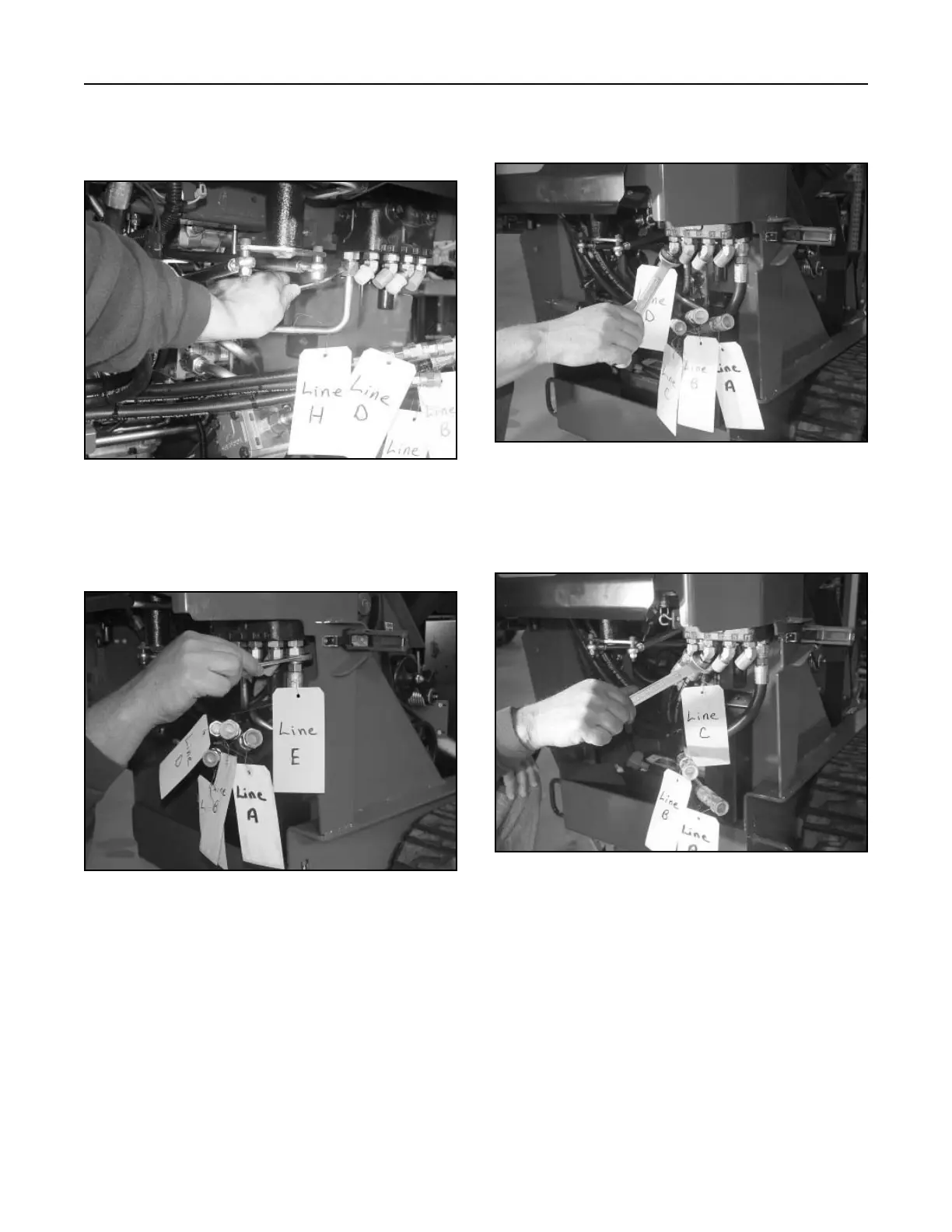
3. (Fig. 197, Ref. H) Install the hydraulic drain
line from the T-fitting on the oil filter base to the
hydraulic lift valve and tighten.
5. (Fig. 199, Ref. D) Install the hydraulic hose to the
fitting on the hydraulic lift valve and tighten.
Figure 197 DSC-0933
Figure 199 DSC-0929
4. (Fig. 198, Ref. E) Install the hydraulic hose from
the gear pump to the hydraulic lift valve and
tighten.
6. (Fig. 200, Ref. C) Install the hydraulic hose to the
fitting on the hydraulic lift valve and tighten.
Figure 198 DSC-0932
Figure 200 DSC-0928

Table of Contents

Other manuals for Toro Dingo TX 413

Questions and Answers:

Question and Answer IconNeed help?

Do you have a question about the Toro Dingo TX 413 and is the answer not in the manual?

Toro Dingo TX 413 Specifications

General IconGeneral
BrandToro
ModelDingo TX 413
CategoryCompact Loader
LanguageEnglish

Related product manuals