g033329
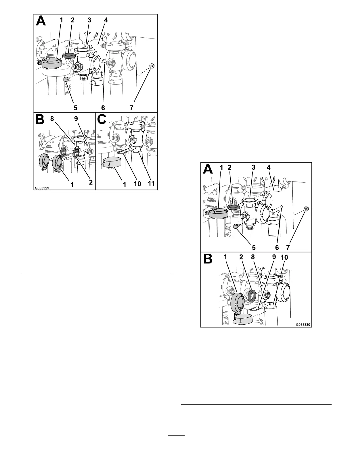
Figure76
1.Flangeclamp7.Flangedlocknut
2.Gasket8.Flange(rate-controlvalve)
3.Manifold(agitationvalve)9.Flange(master-section
valve)
4.Flange
(manifold—agitation-bypass
valve)
10.Retainer
5.Flanged-headbolt
11.Socket(outlettting)
6.Valvemount
2.Assembletheagitation-bypassvalve,gasket,
andagitation-valvemanifoldwithaclamp
tightenedbyhand(Figure76A).
3.Alignagasketbetweentheangesofthe
rate-controlvalveandtheagitation-valve
manifold(Figure76B).
4.Assemblethegasketandagitation-valve
manifoldwithaclamptightenedbyhand(Figure
76B).
5.Alignagasketbetweentheangesofthe
agitation-valvemanifoldandthemaster-section
valve(Figure76B).
6.Assembletheagitation-valvemanifold,gasket,
andmaster-sectionvalvewithaclamptightened
byhand(Figure76B).
7.Assembletheagitation-valvemanifoldand
socketwithaclamptightenedbyhand(Figure
76C).
8.Securetheend-capttingtotheoutletttingby
insertingaretainerintothesocketoftheoutlet
tting(Figure76C).
9.Assembletheagitationvalvetothevalvemount
withtheanged-headboltandangedlocknut
thatyouremovedinstep3ofRemovingthe
Agitation-ManifoldValve(page59)andtorque
thenutandboltto1017to1243N∙cm(90to
110in-lb).
10.Ifyouloosenedthemountinghardwareforthe
master-sectionvalve,tightenthenutandboltto
1978to2542N∙cm(175to225in-lb).
Installingthe
Master-Section-ManifoldValve
1.Aligntheangeofthemaster-section-valve
manifold,1gasket,andtheangeofthe
master-section-bypassvalve(Figure77A).
g033330
Figure77
1.Flangeclamp6.Valvemount
2.Gasket
7.Flangedlocknut
3.Manifold(master-section
valve)
8.Flange(agitationvalve)
4.Flange
(bypass—master-section
valve)
9.Retainer
5.Flanged-headbolt
10.Socket(outlettting)
65
 Loading...


