g213726
Figure14
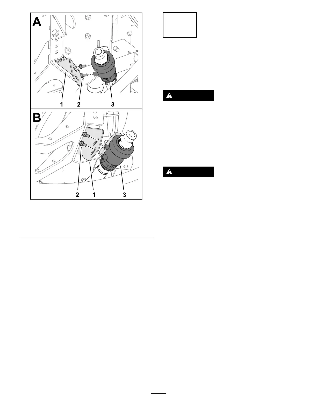
1.Drainvalve3.Drain-valvebracket
2.Flange-headbolt(5/16x
5/8inch)
3.Removethe2ange-headbolt(5/16x5/8inch)
fromthecaseofthedrainvalve(Figure14).
4.Assemblethedrainvalvetothedrain-valve
bracket(Figure14B)withthe2ange-headbolts
(5/16x5/8inch)thatyouremovedinstep3.
5.Tighten2anged-headboltsbyhand(Figure
14B).
6
DisconnectingtheBattery
NoPartsRequired
Procedure
WARNING
Incorrectbatterycableroutingcoulddamage
thesprayerandcablescausingsparks.
Sparkscancausethebatterygassesto
explode,resultinginpersonalinjury.
Alwaysdisconnectthenegative(black)
batterycablebeforedisconnectingthe
positive(red)cable.
WARNING
Batteryterminalsormetaltoolscouldshort
againstmetalsprayercomponentscausing
sparks.Sparkscancausethebatterygasses
toexplode,resultinginpersonalinjury.
•Whenremovingorinstallingthebattery,
donotallowthebatteryterminalstotouch
anymetalpartsofthesprayer.
•Donotallowmetaltoolstoshortbetween
thebatteryterminalsandmetalpartsof
thesprayer.
1.Squeezethesidesofthebatterycovertorelease
thetabsfromtheslotsinthebatterybase,and
removethebatterycoverfromthebatterybase
(Figure15).
21