2.Connectthe3-pinconnectorofthewireharness
ofthemachineforspeedsensorintothe
3-socketconnectorofthesprayerharnessfor
thespeedsensor(Figure17).
8
CouplingtheSprayerPump
NoPartsRequired
Procedure
•ForHD-seriesmodelswithamanualtransmission,
couplethePTOshafttothetransaxlePTO;refer
totheInstallationInstructionsfortheMultiProWM
TurfSprayerFinishingKit,ManualWorkmanUtility
Vehicle.
•ForHDX-Automodel—connectthehydraulic
motorhosestothequick-disconnectttingsatthe
high-owhydraulicpanel;refertotheInstallation
InstructionsfortheMultiProWMTurfSprayer
FinishingKit,AutomaticWorkmanUtilityVehicle.
9
InstallingtheControl
ConsoletotheMachine
Partsneededforthisprocedure:
1
Consolemountingbracket
3
Flangelocknut(5/16inch)
3
Flange-headbolt(5/16inch)
2Plasticbushing
1
Controlconsole
1
Spring-clippin
1Handknob
InstallingtheConsoleMounting
Bracket
Note:OnsomeWorkmanvehicles,thecontrolmount
plateisattachedtothedashboardatthesamelocation
wherethebracketfortheoptionalhandthrottlekitis
mounted.Ifthehandthrottlekitisinstalled,youneed
toremovethebracketofthehandthrottleassembly
fromthedashboard,alignthecontrolmountplateto
thedash,andinstallthehandthrottlebracketontop
ofthecontrolmountplate.RefertotheHandThrottle
KitInstallationInstructionsfordirectionsonremoving
andinstallingthehandthrottleassembly.
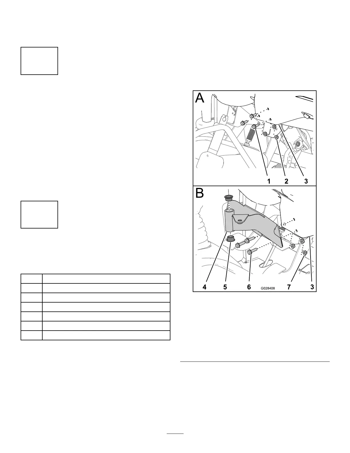
1.Removethe3boltsand3nutsthatsecurethe
lower-centerportionofthedashpaneltothe
dashsupportbracket(Figure18).
Note:SomeolderWorkmanmachinesmayuse
4boltsandangenuts.
Note:Discardtheboltsandnuts.
g028408
Figure18
1.Bolt
5.Bushing(plastic)
2.Nut
6.Flange-headbolts(5/16x
1inch)
3.Cashpanel(lowercenter
area)
7.Flangelocknuts(5/16
inch)
4.Mountingbracket(control
console)
2.Aligntheholesinthemountingbracketforthe
controlconsolewiththeholesinthedashand
supportbracket(Figure18).
3.Assemblethemountingbracketdashpaneland
supportbracketwiththe3ange-headbolts
(5/16x1inch)and3angelocknuts(5/16inch).
4.Torquethenutsandboltsto(Figure18).
23