g213727
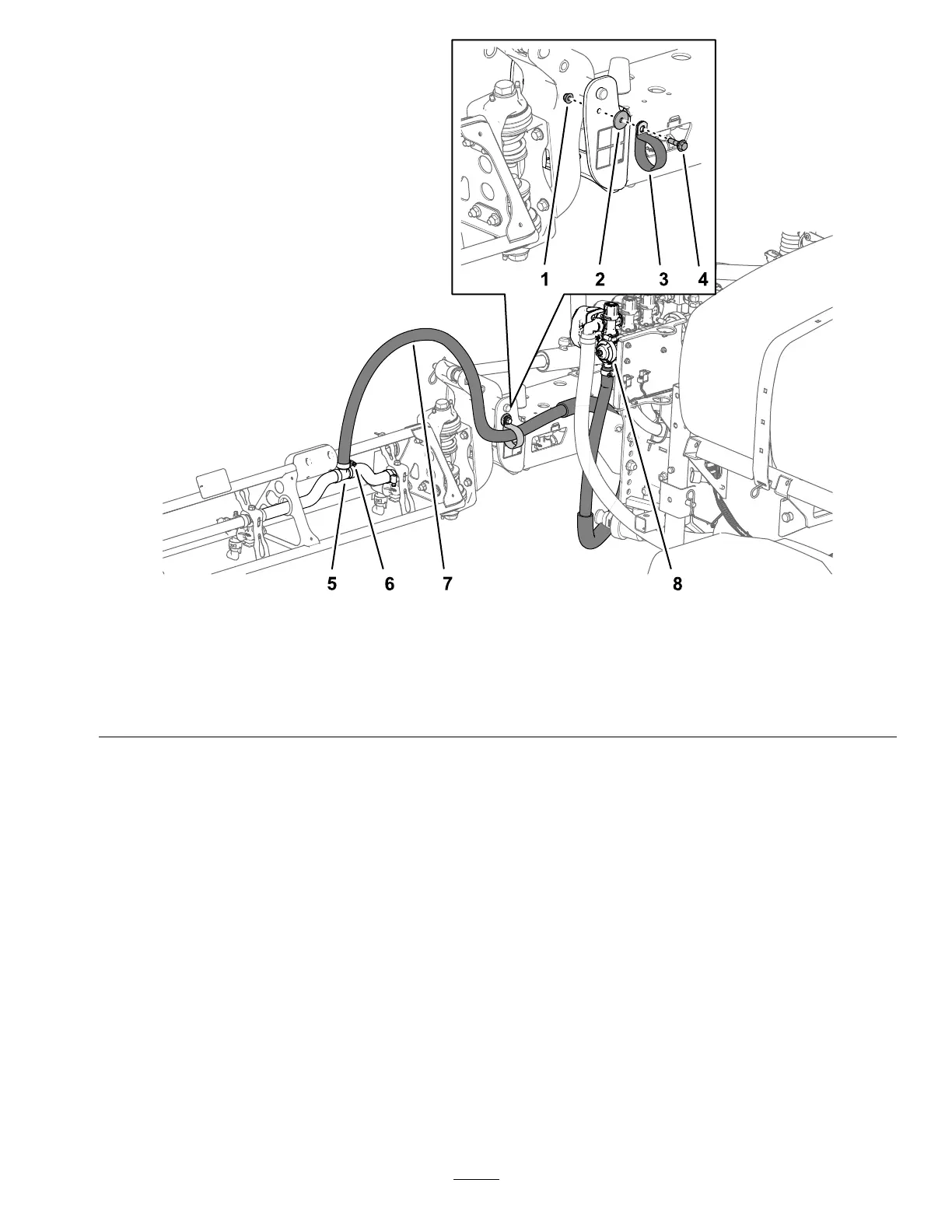
Figure43
Hose—RightBoomSection
1.Nut
4.Shoulderbolt
7.Right-boomhose
2.Washer
5.T-tting
8.Right-sectionvalve
3.R-clamp6.Hoseclamp
2.Securetheboomhosestothefrontsideofthe
centerboomsection(Figure42andFigure43)
with1R-clamp,1shoulderbolt(5/16x1inch),1
locknut(5/16inch),and1washer(5/16inch).
3.Installtheboomsectionhoseoverthebarbed
T-ttingattheboomsectionandsecurethehose
withahoseclamp(Figure42andFigure43).
Note:Applyacoatofliquidsoaptothehose
barboftheteettingtoeaseinstallationofthe
hose.
4.Repeatsteps1through3onthehosetothe
boomsectionontheothersideofthesprayer.
35