g435860
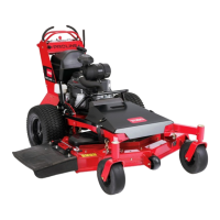
Figure 99
1. Adjustment bolt 3. T ie-rod
2. Jam nut
C. T o raise the back of the cutting-unit, loosen
the jam nuts for the tie-rods on both sides of
the cutting unit ( Figure 99 and Figure 100 ).
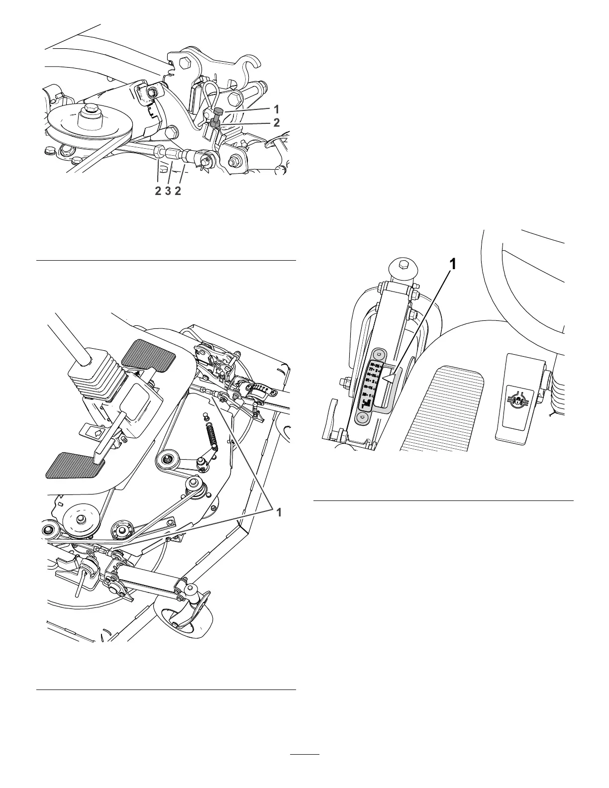
g435865
Figure 100
1. Jam nuts and tie-rods
D. Rotate the tie-rods until the rear-most point
of the cutting unit is 5 to 10 mm (0.20 inches
to 0.39 inches) higher than the front-most
point of the cutting unit.
Note: Ensure both tie-rods are adjusted
the same length.
6. T ighten the jam nuts for the tie-rods ( Figure 99 ).
7. Check the cutting unit for left to right level; refer
to Leveling the Cutting Unit Left to Right ( page
76 ) .
Leveling the Cutting Unit Left to
Right
1. Adjust the height of cut to the 64 mm (2-1/2 inch)
position ( Figure 101 ).
g474738
Figure 101
1. Height-of-cut indicator [64 mm (2-1/2 inch)]
2. Shut of f the engine and remove the key .
3. Align a wing blade to the outermost position
( Figure 102 ).
76