g435859
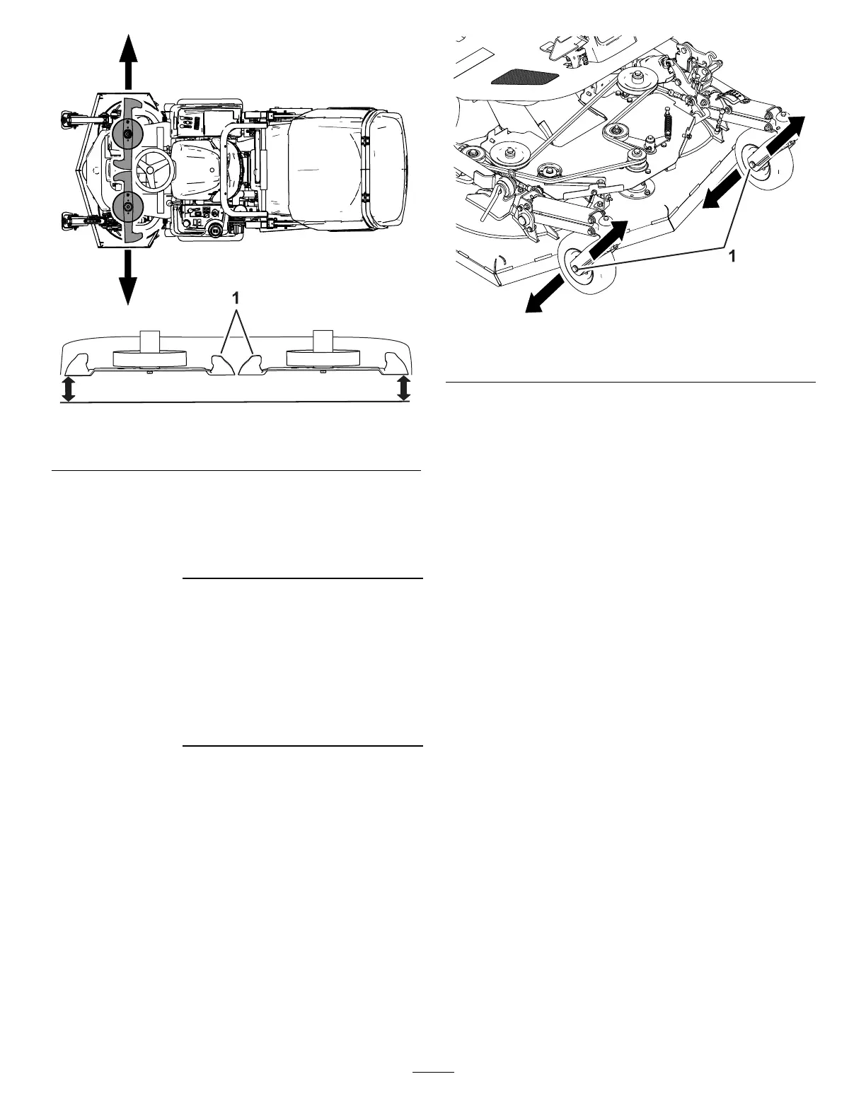
Figure 102
1. Blades
4. Measure the distance between the ground and
the outermost point of the cutting edge of the
blade ( Figure 102 ).
Record your
measurement here:
5. Align the wing blade at the other side of the
cutting unit to the outermost position ( Figure
102 ).
6. Measure the distance between the ground and
the outermost point of the blade cutting edge
with a gauge block ( Figure 102 ).
Record your
measurement here:
7. If the dif ference between the measurements
is greater than 3.2 mm (1/8 inch), perform the
following:
A. Loosen the caster-wheel bolt on one side
( Figure 103 ).
g436284
Figure 103
1. Caster-wheel bolt
B. Adjust the caster wheel bolt in the slot and
tighten the bolt ( Figure 103 ).
Note: If needed, adjust the opposite side
caster wheel.
8. Measure the outermost point of the blade cutting
edges ( Figure 102 ).
9. Repeat the adjustment of the caster wheels until
the dif ference between the measurements is 3.2
mm (1/8 inch) or less.
10. Install the belt cover; refer to Installing the Belt
Cover ( page 73 ) .
77