Rev. A
4WD Rear Axle
Unit S/N 200000001 & Up
Reelmaster 5200-D/5400-D 4WD Rear AxlePage 9.1 - 13
(Unit Serial No. 200000001 & Up)
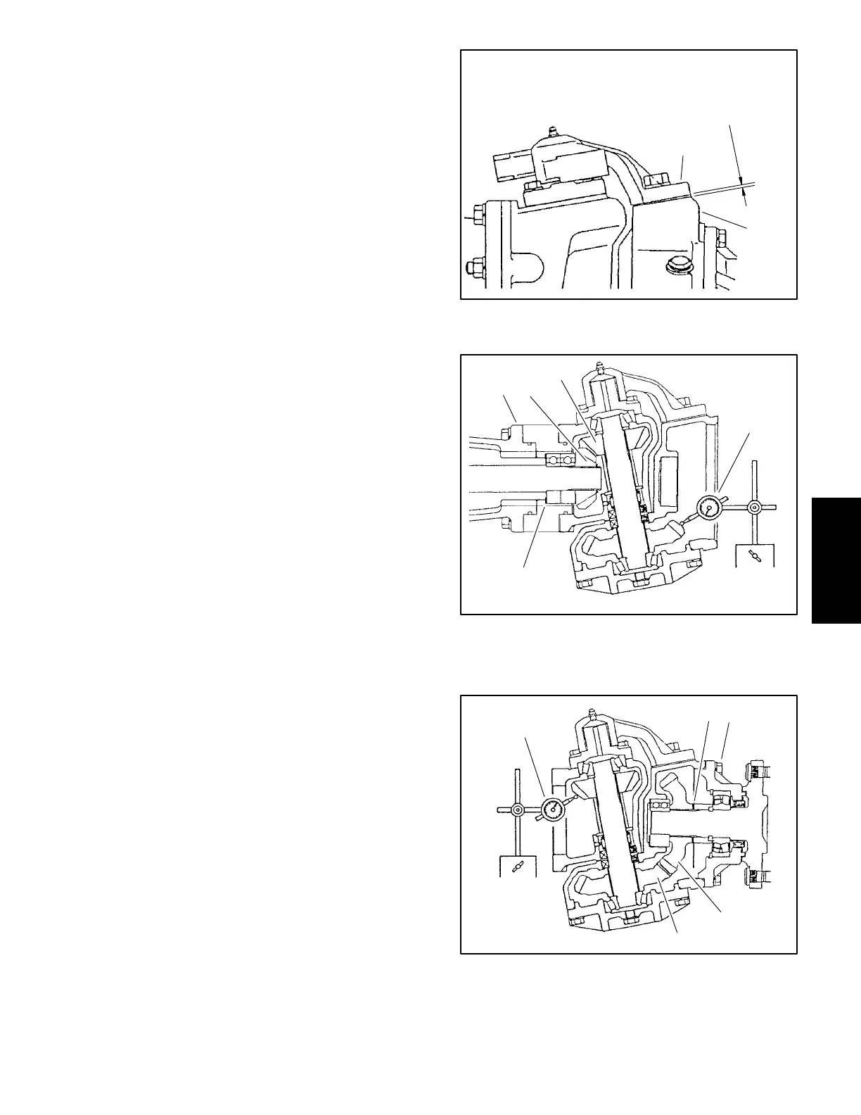
5. Lubricate the axle case support bushing with a thin
coat of grease and slide support all the way onto knuckle
pin without any support shims (Fig. 18).
6. Use a feeler gauge to measure axle case to axle
case support clearance (Fig. 18).
7. Install axle case support with correct shims.
DESIRED SHIM THICKNESS:
Axle case to axle case support clearance + 0.000
to 0.008 in. (0.0 to 0.2 mm)
Note: Axle case support shims are available in
0.004 in. (0.1 mm), 0.008 in. (0.2 mm), and 0.016 in. (0.4
mm) thickness.
8. Apply heavy strength Loctite thread locker on
threads and tighten support screws to 57 to 67 ft-lbs. (77
to 91 Nm).
IMPORTANT: Correct engagement between bevel
gears is critical to axle performance and durability.
9. Temporarily install the bevel gear case/axle case as-
sembly on the axle support. Position a dial indicator at
the tooths center. Prevent the axle from turning and
measure the upper bevel gear to differential shaft gear
backlash (Fig. 19).
UPPER BEVEL GEAR BACKLASH:
0.004 to 0.016 in. (0.10 to 0.40 mm)
10.Adjust backlash by increasing or reducing axle bear-
ing shim thickness (see Differential Shafts in this section
of this manual).
Note: Axle bearing shims are available in 0.004 in.
(0.1 mm), 0.008 in. (0.2 mm), and 0.020 in. (0.5 mm)
thickness.
11.Remove the bevel gear case/axle case assembly
from the axle support. Coat a new O-ring with grease
and temporarily install the axle cover assembly. Position
a dial indicator at the tooths center. Prevent the axle
from turning and measure the lower bevel gear to axle
gear backlash (Fig. 20).
LOWER BEVEL GEAR BACKLASH:
0.004 to 0.016 in. (0.10 to 0.40 mm)
12.Adjust backlash by increasing or reducing axle bear-
ing shim thickness (see Axle Shafts in this section of this
manual).
Note: Axle bearing shims are available in 0.008 in.
(0.2 mm), 0.012 in. (0.3 mm), and 0.020 in. (0.5 mm)
thickness.
1. Axle case support 2. Axle case
Figure 18
1
2
AXLE CASE
TO
AXLE CASE SUPPORT
CLEARANCE
1. Axle support
2. Upper bevel gear
3. Differential shaft gear
4. Dial indicator
5. Axle bearing shims
Figure 19
1
2
3
4
5
1. Axle cover assembly
2. Lower bevel gear
3. Axle gear
4. Dial indicator
5. Axle bearing shims
Figure 20
1
2
3
4
5

 Loading...


