Reelmaster 5200-D/5400-DHydraulic System Page 4 - 76
Lift Cylinders
Removal
1. Read the General Precautions for Removing and
Installing Hydraulic System Components at the begin-
ning of the Service and Repairs section of this chapter.
2. Disconnect hydraulic hoses from lift cylinder.
3. Remove front right or left lift cylinder.
A. Remove retaining ring from the cylinder rod end
pin. Remove cylinder pin with remaining retaining
ring and thrust washers from the lift arm and cylinder
clevis (Fig. 96 and 95).
B. Remove self tapping screw from cylinder pin and
carrier frame. Pull cylinder pin from carrier frame and
cylinder clevis (Fig. 96).
4. Remove front center lift cylinder (Fig. 97).
A. Remove retaining ring from the cylinder rod end
pin. Remove cylinder pin with remaining retaining
ring and thrust washers from the lift arm and cylinder
clevis.
B. Remove self tapping screw from cylinder pin and
carrier frame. Pull cylinder pin from carrier frame and
cylinder clevis.
5. Remove rear lift cylinder (Fig. 98).
A. Remove retaining ring from the cylinder rod end
pin. Remove cylinder pin with remaining retaining
ring and thrust washers from the lift arm and cylinder
clevis.
B. Remove retaining ring from the cylinder cap end
pin. Remove cylinder pin with remaining retaining
ring from the frame and cylinder clevis.
Installation
1. Install rear lift cylinder (Fig. 98).
A. Insert cylinder pin with ratcheted retaining ring
through the frame and cylinder clevis. Secure retain-
ing ring to the cylinder cap end pin.
B. Insert cylinder pin with attached retaining ring
and thrust washer through the lift arm and cylinder
clevis. Secure thrust washer and retaining ring to the
cylinder rod end pin.
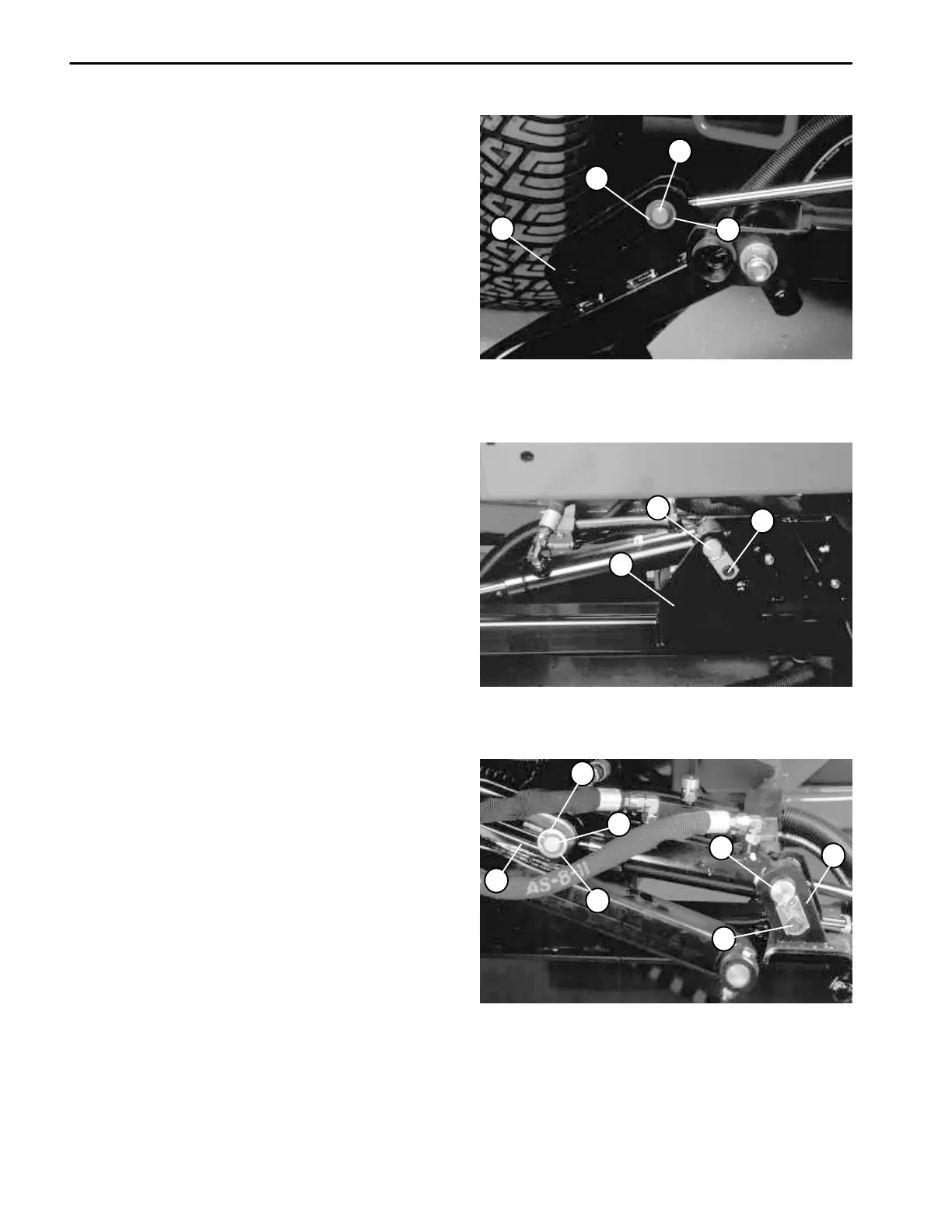
1. Retaining ring
2. Cylinder rod end pin
3. Thrust washer
4. Lift arm
Figure 95
1
2
3
4
1. Self tapping screw
2. Cylinder pin (long)
3. Carrier frame
Figure 96
2
1
3
1. Self tapping screw
2. Cylinder pin (short)
3. Carrier frame
4. Retaining ring
5. Cylinder rod end pin
6. Thrust washer
7. Lift arm
Figure 97
2
1
3
4
5
6
7

 Loading...


