Reelmaster 5200-D/5400-DHydraulic System Page 4 - 32
TEST NO. 7: Gear Pump Section (P3) Flow and Relief Valve Pressure
(Using Tester with Pressure Gauges and Flow Meter)
1. Make sure hydraulic oil is at normal operating tem-
perature by operating the machine for approximately 10
minutes.
2. Make sure machine is parked on a level surface with
the cutting units lowered and off. Make sure engine is
off.
CAUTION
Prevent personal injury and/or damage to equip-
ment. Read all WARNINGS, CAUTIONS, and Pre-
cautions for Hydraulic Testing at the beginning
of this section.
3. With the engine off and cutting units lowered, install
tester in series between pressure hose and the gear
pump section P3 (Fig. 25). Make sure the tester flow
control valve is OPEN.
IMPORTANT: Make sure that the oil flow indicator
arrow on the flow gauge is showing that the oil will
flow from the pump, through the tester and into the
valve block.
IMPORTANT: The pump is a positive displacement
type. If pump flow is completely restricted or
stopped, damage to the pump, tester or other com-
ponents could occur.
4. Make sure the parking brake is engaged. Start the
engine and move throttle to full speed (3200 RPM). DO
NOT engage the cutting units.
5. While watching pressure gauges, slowly close flow
control valve until 1000 PSI is obtained on gauge. Verify
pump speed at 3200 RPM at the transmission input
shaft from the engine.
TESTER READING: Flow not less than 3.5 GPM at
1000 PSI.
6. If flow was lower than 3.5 GPM or a pressure of 1000
PSI cannot be obtained, check for restriction in pump in-
take line. If not restricted, verify relief setting first, then
remove pump and repair or replace as necessary.
7. While watching pressure gauges, slowly close flow
control valve further until 1250 PSI is maintained as the
relief valve lifts.
TESTER READING: Relief valve setting of 1250 PSI.
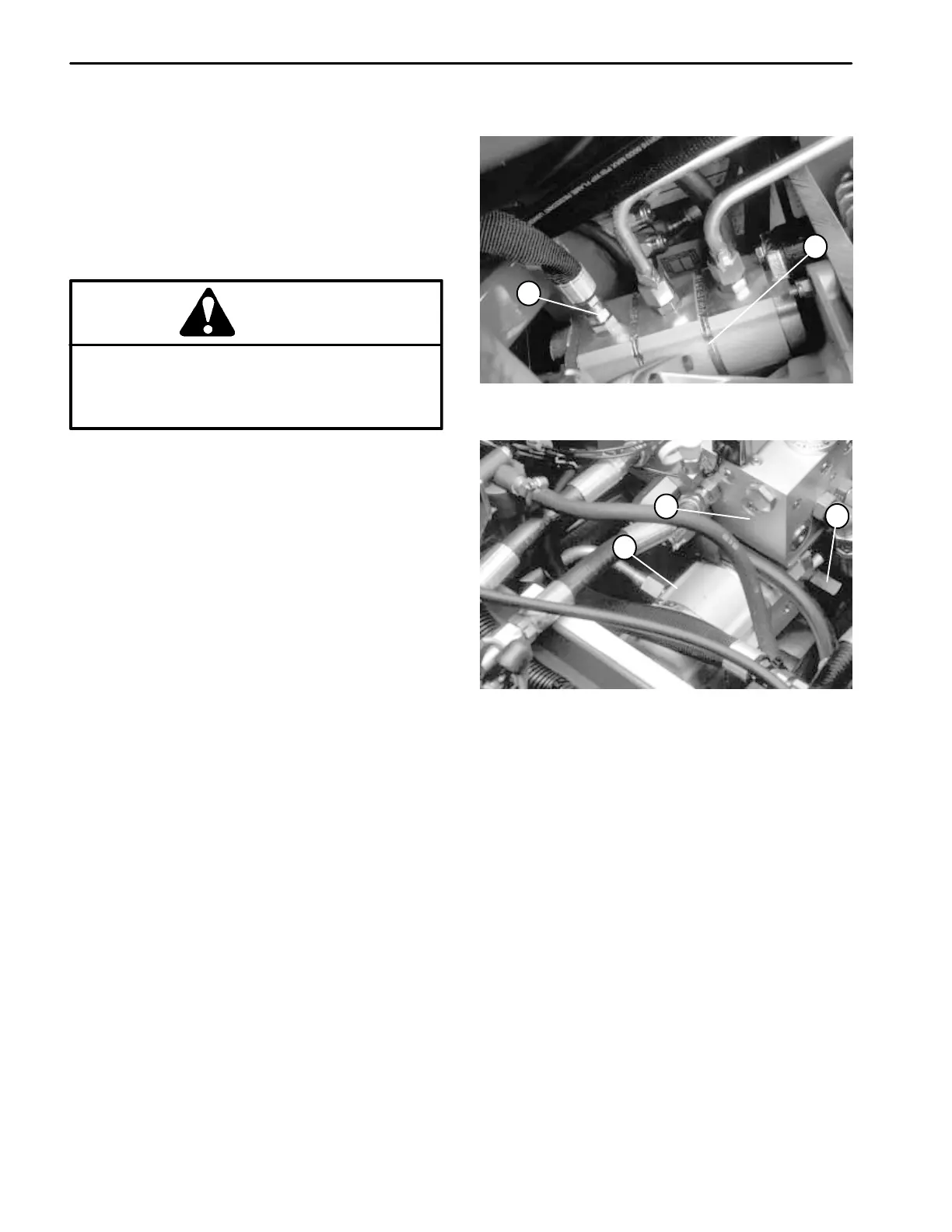
1. Outlet to steering 2. Gear pump
Figure 25
1
2
1. Gear pump
2. Relief valve
3. Manifold block
Figure 26
1
2
3
8. If pressure is maintained below 1250 PSI or pressure
goes beyond 1250 PSI, adjust relief valve by removing
the cap and turning the adjustment screw. Turn adjuster
clockwise to increase pressure and counterclockwise to
decrease pressure (Fig. 26).
9. Stop engine. Remove tester and reinstall hoses.

 Loading...


