STE 80720
– 10-8 –
OPERATOR’S MANUAL
series Robot Controller
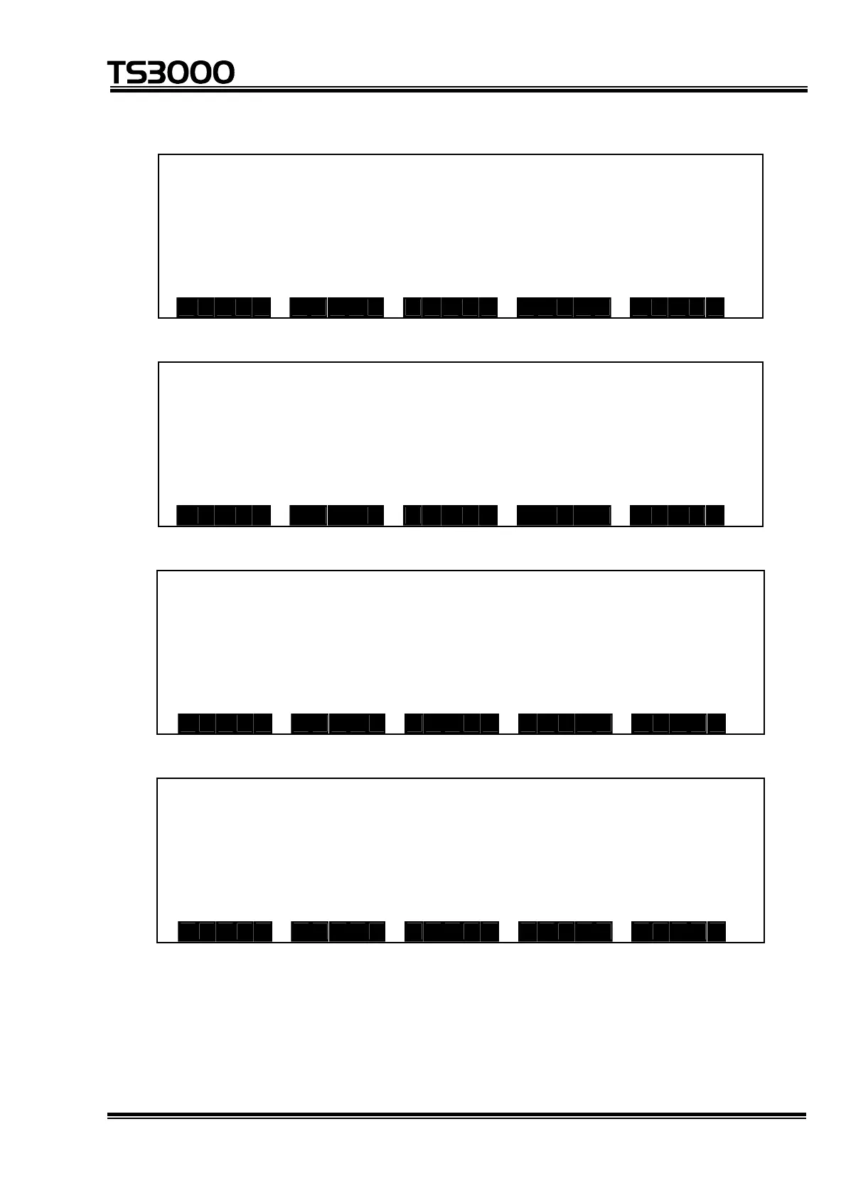
Page 2 (expansion input)
I / O M o n i t o r ( E x t e d I N ) 2 / 5
1 10 11 20
D I N 1 0 * 0 0 000 00000 0000 0 0 0 000
1 2 * 0 0 000 00000 0000 0 0 0 000
1 4 * 0 0 000 00000 0000 0 0 0 000
1 6 * 0 0 0 0
D I N D O U T S Y S
Page 3 (system input)
I / O M o n i t o r ( S y s t e m I N ) 3 / 5
1 10 11 20
D I N 2 0 * 0 0 000 00000 0000 0 0 0 000
2 2 * 0 0 000 00000 0000 0 0 0 000
2 4 * 0 0 000 00000 0000 0 0 0 000
2 6 * 0 0 0 0
D I N D O U T S Y S
Page 4 (field bus input 1)
I / O M o n i t o r ( F i e l d b u s 1 I N ) 4 / 5
1 10 11 20
D I N 3 0 * 0 0 0 0 0 0 0 0 0 0 0 0 0 0 0 0 0 0 0 0
3 2 * 0 0 0 0 0 0 0 0 0 0 0 0 0 0 0 0 0 0 0 0
3 4 * 0 0 0 0 0 0 0 0 0 0 0 0 0 0 0 0 0 0 0 0
3 6 * 0 0 0 0
D I N D O U T S Y S
Page 5 (field bus input 2)
I / O M o n i t o r ( F i e l d b u s 2 I N ) 5 / 5
1 10 11 20
D I N 4 0 * 0 0 0 0 0 0 0 0 0 0 0 0 0 0 0 0 0 0 0 0
4 2 * 0 0 0 0 0 0 0 0 0 0 0 0 0 0 0 0 0 0 0 0
4 4 * 0 0 0 0 0 0 0 0 0 0 0 0 0 0 0 0 0 0 0 0
4 6 * 0 0 0 0
D I N D O U T S Y S
• The I/O signal status is represented by "1" for open contacts and by "0" for
close contacts.
• One line contains 20 signals which are separated at every 5 signals, and the
number of the signal at the head of the signal string is displayed at the left
end of the line.

 Loading...


