TECHNICAL INFORMATION
Copyright Trace Engineering Company, Inc.
5916 - 195th Street N.E.
Arlington, WA 98223
Telephone: 360/435-8826
Fax: 360/435-2229
www.traceengineering.com
PS Series Inverter/Charger
Part No. 3597
Rev. D: November 23, 1999
Page
101
BATTERY CARE AND MAINTENANCE
If you have read the battery charger mode section of this manual, you already have a good idea of the
stages of battery charging that combine to promote fast charging and ensure long battery life. Basically,
there are five charger-related considerations to properly care for your batteries.
• Charge Rate - The maximum safe charge rate is related to the size and type of your batteries.
Standard vented lead acid batteries (with battery caps) can be charged at a high rate - equal to their
capacity. Small batteries may require a lower charge rate. Check with the battery manufacturer.
Adjust the MAX CHARGE AMPS AC setting to control the charging rate.
• Bulk Voltage - This is the maximum voltage the batteries reach during the normal charging process.
Gel cell batteries are usually set to a lower value, while non-sealed batteries are set to the higher.
Adjust the BULK VOLTS DC setting to control the battery voltage during the BULK and
ABSORPTION stages.
• Float Voltage - The batteries experience less gassing if they are maintained at a lower voltage than
the voltage at which they are charged. Adjust the FLOAT VOLTS DC setting to control the battery
voltage.
• Temperature Compensation - Temperature affects the optimum voltage values for the bulk and float
charging stages. The Battery Temperature Sensor (BTS) automatically fine-tunes these voltages for
you.
• Equalization (Non-Sealed Batteries Only) - Every month or two, batteries may need to be
"equalized. " (A fancy term for over-charged.) Since the individual battery cells are not exactly
identical, some may still have sulfate on their plates after a complete charge cycle. On the other
hand, if the batteries never received a full charge, all plates will have sulfate left on them. If the sulfate
remains on the plates for an extended period of time, it will harden and seal off a percentage of the
plate area, reducing the capacity of the battery. By equalizing the batteries, the entire sulfate is
removed from the plates. Additionally, the gassing that result stirs up the electrolyte which tends to
stratify. Stratification concentrates the sulfuric acid in the bottom of the cell while the top becomes
watery. This corrodes the plates. Equalization is accomplished by charging batteries above a voltage
of 2.5 VDC per cell. This is over 15 VDC for a 12 VDC system, 30 for a 24 VDC system and 60 for a
48 VDC system.
CAUTION: Equalization should be done only with standard electrolyte batteries. If you have
sealed or gel cell batteries, check first with the battery manufacturer before equalizing. DC loads
should be disconnected before equalization to protect them from damage by the high battery voltage
involved.
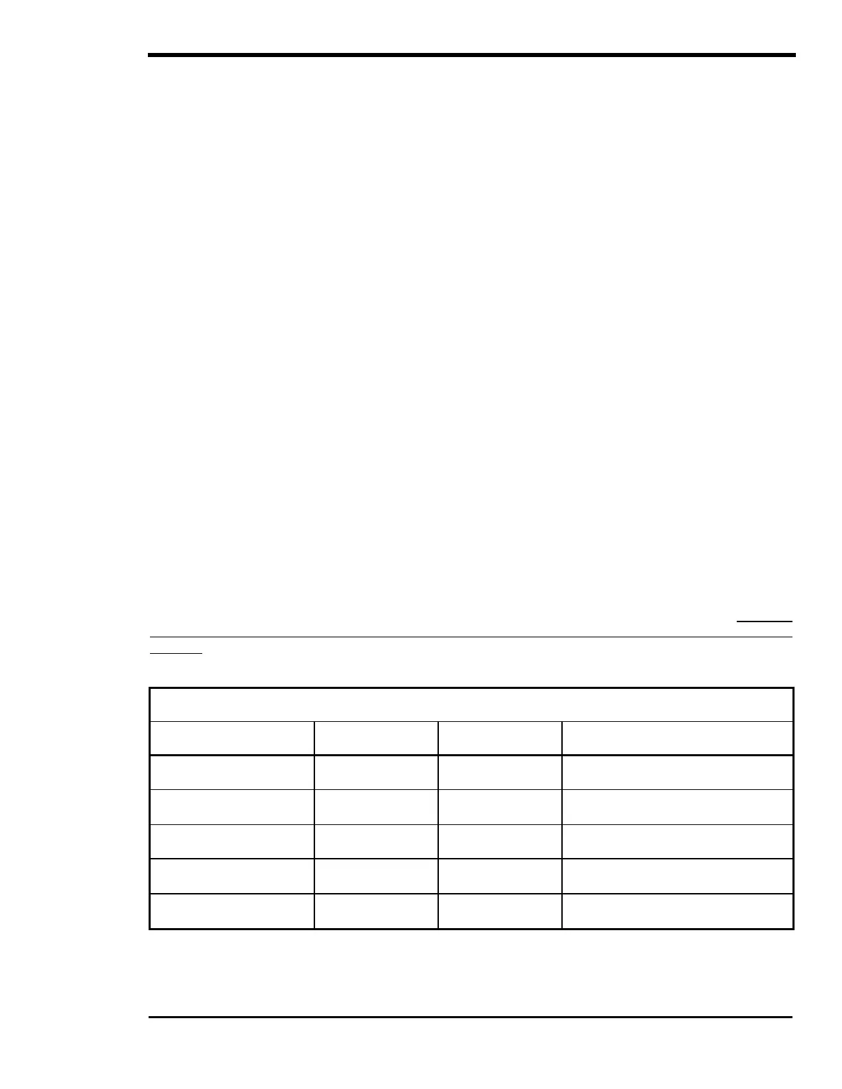
Table 8, Battery Charging: Charging Setpoints
TYPICAL BULK AND FLOAT SETPOINTS FOR COMMON BATTERY TYPES
Battery Type Bulk Volts Float Volts Equalizing Charge Process
Sealed Gel
Lead Acid battery
14.1 VDC BULK 13.6 VDC FLOAT Not Recommended - Consult manufacturer
A.G.M.
Lead Acid battery
14.4 VDC BULK 13.4 VDC FLOAT Charge to 15.5 VDC or as per manufacturer
Maintenance-Free RV/Marine
Lead Calcium Battery
14.4 VDC BULK 13.4 VDC FLOAT Not Recommended - Consult manufacturer
Deep-Cycle, Liquid Electrolyte
Lead Antimony Battery
14.6 VDC BULK 13.4 VDC FLOAT Charge to 15.5 VDC or as per manufacturer
NiCad or NiFe Alkaline Battery
(using 10 cells in series)
16.0 VDC BULK 14.5 VDC FLOAT Consult manufacturer
Note: Values shown are for 12-volt systems. For 24-volt systems, multiply the settings shown by 2. For
48-volt systems, multiply the settings shown by 4. These settings are guidelines, refer to your
battery manufacturer for specific settings.