CONTROLS, INDICATORS AND COMPONENTS
Copyright Trace Engineering Company, Inc.
5916 - 195th Street N.E.
Arlington, WA 98223
Telephone: 360/435-8826
Fax: 360/435-2229
www.traceengineering.com
PS Series Inverter/Charger
Part No. 3597
Rev. D: November 23, 1999
Page
13
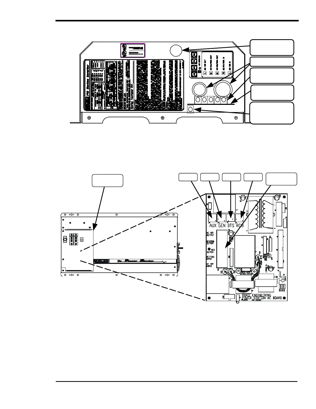
AC SIDE
Figure 5, PS Series AC Side
AC CIRCUIT BOARD
By removing the Access Panel, you will be able to gain access to the AC circuit board, which includes the
AC terminal block and four RJ11 jacks for connecting specific optional components.
Figure 6, AC Circuit Board
AUX - RJ11 connection jack for the optional plug-in Auxiliary Relay Module. The Auxiliary Relay Module
consists of two voltage-controlled relays and is used to simplify installations that have battery voltage
related tasks to perform. The relays are single pole double throw, five amp relays. Both the normally
closed and normally open contacts are available for each relay. The operation of each relay is individually
controlled and adjustable with a SWRC via the user menu. The auxiliary relays on the AUXILIARY
RELAY MODULE operate independently of the inverter or charger.
Terminal
(located inside)
knockout
AC knockouts
(located inside)
(located inside)
PANEL
BLOCK
RC8AUX GEN BTS