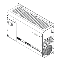
CONTROLS, INDICATORS AND COMPONENTS
Page
12
Copyright Trace Engineering Company, Inc.
5916 - 195th Street N.E.
Arlington, WA 98223
Telephone: 360/435-8826
Fax: 360/435-2229
www.traceengineering.com
PS Series Inverter/Charger
Part No. 3597
Rev. D: November 23, 1999
Over-current: The load requirement has exceeded the maximum output AC amps. To clear this fault,
disconnect the loads and restart the inverter. To restart the inverter after an overcurrent fault condition,
press the On/Off Power Switch only one time. Reconnect the loads one at a time to find the load or
combination of loads that caused the problem. If the inverter will not restart with all the AC loads
disconnected, remove all AC wiring from the terminal block and try to restart again. If it restarts, the
problem is with the wiring. If it does not restart, refer to the other error causes to determine the error.
AC source wired to output: Reports that an AC voltage source was connected directly to the AC output.
This can be caused by improper wiring or incorrect installation of the inverter. This condition is much
worse than a short circuit and may cause damage to the inverter. Disconnect all wiring from the AC input
and output to find the cause. After the cause has been found and corrected, you can restart the inverter
by selecting OFF and then ON or SRCH with the On/Off Power Switch
External error (stacked): A problem has occurred with the series interface cable or one of the inverters
operated in series. Check the cable for damage and replace it to see if the problem is corrected. Also,
check the connecting input and output AC wiring.
ERROR CAUSES (WILL NOT CAUSE AC OUTPUT TO BE DISCONNECTED).
Low AC input voltage: Your inverter/charger monitors single cycle voltage problems from the AC
source. The low AC voltage level is determined by the SET INPUT LOWER LIMIT VAC setting. If the AC
voltage falls below this setting the INVERT (yellow) LED will flash rapidly and remain on for 3 minutes.
This error is an advisory error only and will not drop the AC input.
High AC input voltage: Your inverter/charger monitors single cycle voltage problems from the AC
source. The high AC voltage level is determined by the SET INPUT UPPER LIMIT VAC setting. If the AC
voltage rises above this setting the INVERT (yellow) LED will flash rapidly and remain on for 3 minutes.
This error is an advisory error only and will not drop the AC input.
Generator failed to start: Indicates that the automatic generator start system was not able to
successfully start the generator. The system completes five start cycles and requires that the generator
operate for a minimum of 5 minutes before the starting attempts counter is cleared. To manually clear this
error, press the green GEN MENU button on the SWRC to access the SET GENERATOR menu item,
then select OFF and then AUTO or ON.
Generator stopped due to V/F: Indicates that the automatic generator start system was not able to
successfully connect to the generator after it was running. If the generator runs for 10 minutes without
operating in the AC voltage and frequency tolerance windows, then the automatic start system stops the
generator and indicates an error condition. To manually clear this error, press the green GEN MENU button
on the SWRC to access the SET GENERATOR menu item, then select OFF and then AUTO or ON.
Gen Max Run Time: An ERROR LED will turn on if the generator run time has exceeded the SET
MAXIMUM RUN TIME setting. This setting is intended to indicate excessive generator operation because
the system has not been able to fully charge the battery. Operating heavy loads while charging, an
unstable generator or even low electrolyte levels in the battery can cause this. If the default value results
in repeated error conditions, then increasing the setting may be necessary for your application. This may
occur with systems that have very large batteries that require long charge periods or systems with small
generators that have limited battery-charging ability. This ERROR is an advisory indication only and will
not stop the generator. You can reset this ERROR LED by selecting OFF and then ON from the SET
GENERATOR menu item, accessed by pressing the green GEN MENU button on the SWRC.
Gen speed error: Indicates that the automatic generator start system has detected that the generator
frequency is not well adjusted. This error condition will cause the red ERROR LED to illuminate, but will
not cause the automatic generator start system to shut down. If the inverter can not synchronize to the
generator after a 10-minute period, then the GEN SPEED ERROR condition will be reached.
ORANGE = CHARGE
ON: This orange LED will be lighted when the unit is charging. The inverter is charging at a constant
current, causing battery voltage to rise near the BULK VOLTS DC setting (default = 14.4 VDC). Once at
this level, the current will taper off until the battery charger has maintained the batteries near the BULK
VOLTS DC setting for the time period of the ABSORPTION TIME setting, at which time it then regulates
the charging process at the FLOAT VOLTS DC setting.

 Loading...