INSTALLATION
Copyright Trace Engineering Company, Inc.
5916 - 195th Street N.E.
Arlington, WA 98223
Telephone: 360/435-8826
Fax: 360/435-2229
www.traceengineering.com
PS Series Inverter/Charger
Part No. 3597
Rev. D: November 23, 1999
Page
25
GROUNDING VS. LIGHTNING
This information is intended to provide basic grounding techniques that will help prevent inverter damage
due to lightning. It is not intended to be a complete course on grounding or a guarantee against protection
during a lightning strike situation. The NEC is the ultimate authority as to legitimate grounding techniques
for your electrical system.
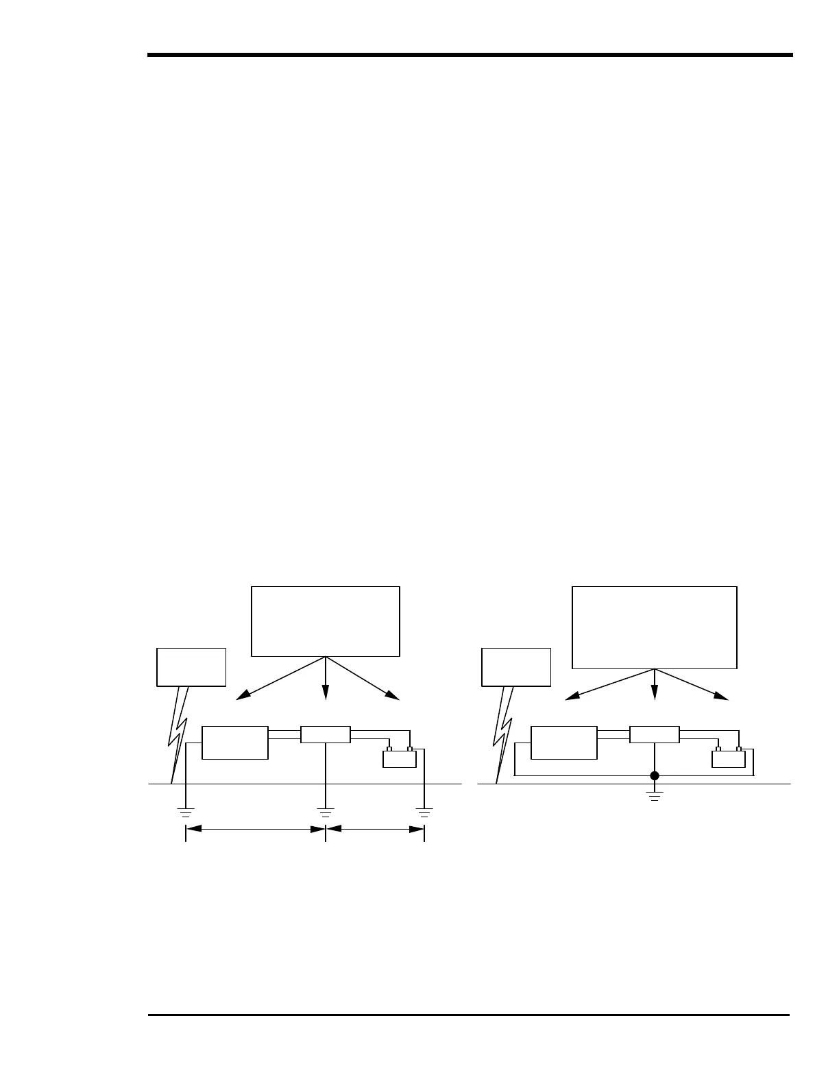
If an electrical system has components grounded at different points in the earth, large voltage
differences will exist between these points during a lightning strike (Figure 14, Multiple Point
Ground System). If this voltage appears between the AC and DC side of the inverter, it will fail. All
Trace inverters are designed to withstand a minimum of 1750 volts between AC and ground, and
500 volts between DC and ground.
ONE GROUND FOR ALL EQUIPMENT
The first step in inverter protection is to make sure that all equipment in the system is physically grounded
at the same location. This assures that there is no voltage potential between grounds in the system
(Figure 15, Single Point Ground System). No voltage means no current flow through the system.
Practically speaking, this would mean connecting the generator and battery grounds together, as well as
the case or “safety” grounds in the system, and then attaching all to the same earth grounding rod (See
the NEC for specific information on grounding requirements, and hardware).
In severe conditions, the generator frame should physically be isolated from the earth by a wood frame or
some other insulating means. This assures that the single point ground system is maintained.
KEEP EQUIPMENT CLOSE TOGETHER
All equipment involved in a system should physically be located as close as possible to one another. This
reduces the potential that is developed between the ground site and the individual components of the
system during a lightning strike. This single point grounding greatly reduces the potential for lightning
damage to electrical equipment.
If you are unable to achieve single-point grounding due to large distances between equipment or other
variables, other means of lightning protection must be considered. Consult a reputable lightning
protection company.
Figure 14, Multiple Point Ground System Figure 15, Single Point Ground System
Equipment all grounded at
same point. No voltage
across system, and no
current flow through
equipment and wiring.
Lightning
Strike
GENERATOR INVERTER
BANK
Equipment acts as a
conductor due to
voltage between the
grounds. Bad!
GENERATOR INVERTER
BANK
Ground
Ground
Ground
Lightning
Strike