OPERATION
Page
72
Copyright Trace Engineering Company, Inc.
5916 - 195th Street N.E.
Arlington, WA 98223
Telephone: 360/435-8826
Fax: 360/435-2229
www.traceengineering.com
PS Series Inverter/Charger
Part No. 3597
Rev. D: November 23, 1999
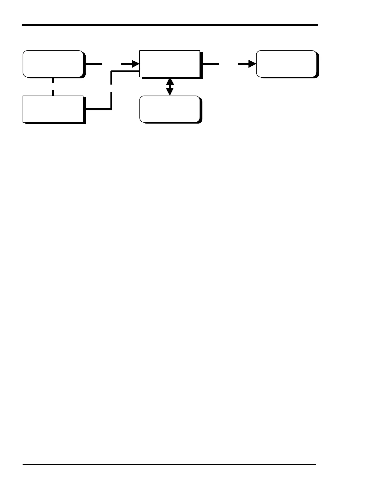
AUTOMATIC GENERATOR CONTROL MODE
IN BRIEF
Automatic start/stop control of a back-up generator can be used with any of the other operating modes
using the optional GEN RELAY MODULE. The SWRC is also required to set-up the different start/stop
control sequences through the menu items under the menu headings GEN AUTO START SETUP (12),
GEN STARTING DETAILS (13) and GENERATOR TIMER (7).
To operate in this mode the system must be set-up as follows:
• Connect the generator AC output out to the inverter's AC HOT IN terminals.
• Set the ‘MAXIMUM AC AMPS IN’ switch to the AC2 position. If the ‘MAXIMUM AC AMPS IN’ switch
is in the AC1 position, the generator will be started automatically but will not be able to synchronize
with the generator.
• Connect the AC loads to the inverter's AC OUTPUT terminals.
• Select AUTO from the SET GENERATOR menu item, accessed by pressing the green GEN MENU
button. The ‘AUTO’ mode is disabled if the ‘CHG’ mode under INVERTER MODE (1) menu heading
is selected.
• Adjust the battery charger parameters to match the requirements of the batteries connected (if the
factory defaults listed in the technical section are not satisfactory).
• Adjust the SET GEN (AC2) AMPS AC menu item located in the AC INPUTS (11) menu heading, to
the continuous output ability of the generator. This allows the generator support feature to function
correctly, preventing the generator from being overloaded. The generator’s output should be derated
for altitude and if propane or natural gas is powering it. It is best to error on the low side for this
setting, or to experiment with higher settings after the system has been operational.
• Adjust the SET INPUT LOWER LIMIT VAC located in the AC INPUTS (11) menu heading, to the
lowest AC voltage that the AC loads can tolerate. If the generator is pulled down to this level while
powering a load, the inverter will back-off its battery charging or even operate in parallel to reduce the
load on the generator. Keep in mind that when the inverter supports the generator it uses energy from
the batteries to power the AC loads. Therefore, when generator support occurs, the batteries can be
discharging instead of recharging even though the generator is running.
• Adjust the SET INPUT UPPER LIMIT VAC located in the AC INPUT (11) menu heading, to the
highest voltage that the generator will be allowed to operate without being considered out of
tolerance. At this voltage the inverter will disconnect to protect the AC loads. When the voltage
returns to the operating window, the inverter will require a minimum of 20 seconds to re-synchronize
and connect the generator to the loads.
INVERTER/
CHARGER
GENERATOR AC LOADS
AC
BATTERY
DC
GEN RELAY
MODULE
CONTROL
CONTROL