OPERATION
Copyright Trace Engineering Company, Inc.
5916 - 195th Street N.E.
Arlington, WA 98223
Telephone: 360/435-8826
Fax: 360/435-2229
www.traceengineering.com
PS Series Inverter/Charger
Part No. 3597
Rev. D: November 23, 1999
Page
63
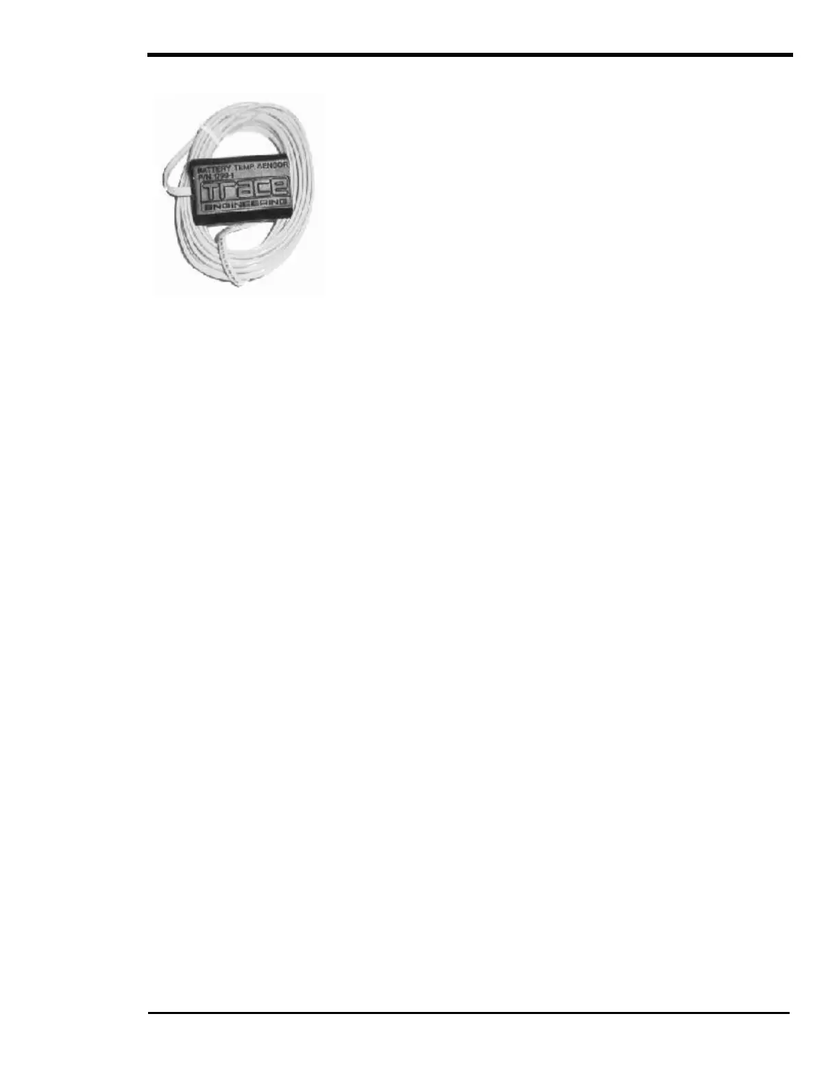
BATTERY TEMPERATURE SENSOR (BTS)
Figure 21, BTS (Battery
Temperature Sensor)
A plug-in external Battery Temperature Sensor (BTS), which is provided,
automatically fine-tunes the charging process of the battery charger in
relation to temperature. When the temperature sensor is installed, the
charge voltage is adjusted either higher or lower than the BULK and
setpoints based on temperature
adjusted charge voltage.
If the temperature sensor is
installed and if the battery is subjected to
large temperature variations, a shorter battery life cycle may be expected.
Install the BTS on the side of the battery below the electrolyte level. It is
best if the sensor is placed between batteries and if the batteries are placed
in an insulated box to reduce the influence of the ambient temperature
outside the battery enclosure. Ventilate the battery box at the highest point
to prevent hydrogen accumulation.
The BTS provided may be extended beyond the standard 15 feet by an
additional 20 feet using standard telephone cables with RJ-11 plugs.
However, locating your batteries more than 35 feet from the inverter
exceeds the recommended distance.
CHARGER ONLY OPERATION
When the CHG mode is selected, the inverter will operate only as a charger. This is useful for unattended
operation where a power failure might allow the inverter to drain the batteries by powering an AC load
unnecessarily. To allow the Charger Only mode, FLT must be selected from the SET GRID USAGE
menu item under the INVERTER SETUP (9) menu heading (FLT is the factory default setting).
This feature is commonly used in marine applications where the inverter operates a refrigeration system
from the batteries. Normally, the engine’s alternators keep the batteries charged. When docked, a shore
cord is connected to the inverter to power the battery charger and run the refrigerator.
AC INPUT REQUIREMENTS
The AC source connected to the inverter’s AC INPUT terminal is used to power both the battery charger
and the AC loads while the inverter is in the battery charger mode. There are several settings, listed
below, that involve the AC INPUT. See Table 4, AC Input Default Settings on page 64, or the USER
SETTINGS WORKSHEET on page 122 for the factory default settings.
When an AC source is applied to the AC HOT INPUT:
From the inverter or RC8: The green AC IN LED indicator will come on once the AC voltage has
been detected at the AC INPUT terminals of the inverter. If the AC source is acceptable, the inverter
will synchronize to the AC source after a delay period has passed. Once synchronized, the inverter
will close an internal relay to connect the AC source to the AC loads, then the inverter will begin to
charge the battery and the orange CHARGE LED indicator will come on.
With the SWRC: The AC1 IN GOOD or AC2 IN GOOD LED indicator will blink slowly once the AC
voltage has been detected. If the AC source is acceptable, the inverter will synchronize to the AC
source after a delay period has passed. Once synchronized, the inverter will close an internal relay to
connect the AC source to the AC loads and the inverter will begin to charge the battery indicated by
the green AC IN GOOD LED indicator turning solid and the orange BULK or green FLOAT LED
indicator turning on.
INPUT AC VOLTAGE
The AC1 and AC2 positions on the ‘MAXIMUM AC AMPS IN’ switch settings share the same upper and
lower limits for restricting connection to an acceptable AC voltage operating window. The AC input voltage
window is typically set to the minimum / maximum range that the AC loads can tolerate - the inverter itself
can operate over an extremely wide voltage range. The upper and lower settings are adjustable with the
SWRC and are located under the AC INPUTS (11) menu heading in the SETUP MENU.