OPERATION
Page
88
Copyright Trace Engineering Company, Inc.
5916 - 195th Street N.E.
Arlington, WA 98223
Telephone: 360/435-8826
Fax: 360/435-2229
www.traceengineering.com
PS Series Inverter/Charger
Part No. 3597
Rev. D: November 23, 1999
OVERVOLTAGE PROTECTION FOR THE BATTERY IN SELL MODE
Normally, the inverter will regulate the charging process of the battery by selling excess power into the
utility grid. The battery will receive a three-stage charge routine as previously described. If the utility grid
is not available (due to an outage or tripped AC input circuit breaker, etc.) or if the inverter shuts off, then
the inverter is not able to sell the excess power and the battery voltage will not be regulated, resulting in
possible overcharging of the battery.
Therefore, a separate control is required to provide overvoltage protection for the battery when an outage
has occurred. The PS Series Inverter/Charger with the optional AUX RELAY MODULE is designed to
control an externally connected power relay that would disconnect the solar array and stop the charging
process. The voltage and hysteresis (difference between opening and closing voltage) are both
adjustable. The external relay can be either a standard mechanical type or a mercury displacement type,
depending on the voltage and current required. The mercury displacement type relay is usually required
when the system voltage is 48 VDC or if the current of the solar array exceeds about 20 amps. Multiple
relays can be used if the solar array is divided into several source circuits (do not parallel relays for higher
current). Another option is to use a charge controller such as the Trace C40. For more on the AUX
RELAY MODULE, see page 128.
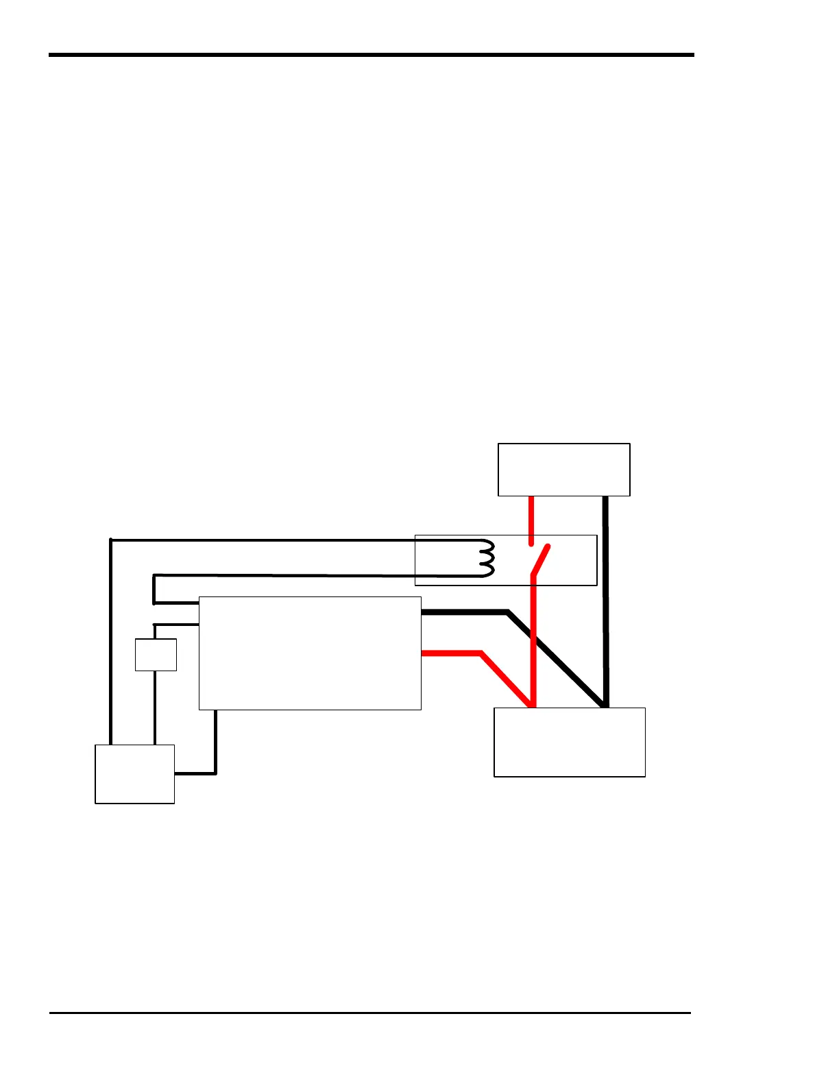
A typically wiring configuration for this overvoltage protection is as follows:
This circuit does draw a small amount of power all of the time to power the coil of the relay. Other circuits
are possible but may have other drawbacks. This circuit provides protection against overcharging the
batteries.
Figure 29, Overvoltage Protection for Battery
OPEN
RELAY
+P -N
COIL
BATTERY BANK
INVERTER
AC OUTPUT - HOT
FUSE
N
+ P
AUX
RELAY
MODULE