OPERATION
Page
64
Copyright Trace Engineering Company, Inc.
5916 - 195th Street N.E.
Arlington, WA 98223
Telephone: 360/435-8826
Fax: 360/435-2229
www.traceengineering.com
PS Series Inverter/Charger
Part No. 3597
Rev. D: November 23, 1999
FREQUENCY
The AC1 position on the ‘MAXIMUM AC AMPS INPUT’ switch is intended for Utility Power to be connected
to the AC INPUT. The frequency tolerance is 53 to 67 Hz for 60 Hz models and 44 to 56 for 50 Hz models.
The typical transfer delay is approximately 30 seconds after the AC HOT INPUT terminal is energized.
When the SELL mode is enabled from the SET GRID USAGE menu item, the transfer delay period is
typically 90 seconds and the frequency tolerance is restricted to 59 to 61 Hz for 60 Hz models and 49 to 51
for 50 Hz models.
The AC2 position on the ‘MAXIMUM AC AMPS INPUT’ switch is intended for a fuel-powered generator to
be connected to the AC INPUT. There is a default 60-second delay before transfer occurs. This delay gives
the generator time to stabilize before being loaded. Frequency tolerance is 53 to 67 Hz for 60 Hz models
and 44 to 56 for 50 Hz models. The AC source must be stable for the inverter to synchronize and connect.
AC CURRENT LEVEL
The maximum current draw into the AC INPUT terminals can also be adjusted in the SET GRID (AC1)
AMPS AC and the SET GEN (AC2) AMPS AC menu items using the SWRC. These inputs are used to “back
off” the battery charger’s AC current draw while other AC loads are being powered through the inverter. This
prevents the overloading of the AC source and nuisance tripping of the AC source circuit breakers.
DELAY PERIOD
With the ‘MAXIMUM AC AMPS INPUT’ switch in the AC1 position, the delay period is fixed at
approximately 30 seconds after the AC source has been applied. If SELL mode is enabled from the SET
GRID USAGE menu item under the INVERTER SETUP (9) menu heading in the SETUP MENU and the
‘MAXIMUM AC AMPS INPUT’ switch is in the AC1 position, the delay reconnection back to the utility
power after an power outage will be for a period of at least 90 seconds. This is not adjustable. The delay
allows the utility distribution system to stabilize before the inverter sells power into it after a utility power
outage has occurred.
With the ‘MAXIMUM AC AMPS INPUT’ switch at the AC2 position, the delay period is adjustable (using
the SWRC) through the SET GEN WARMUP SECONDS menu item under the GEN STARTING
DETAILS (13). This allows the generator to reach a stable operating condition before being loaded. The
default generator warm-up period is 60 seconds. Once warmed up, the inverter synchronizes to the
generator. If the AC source is not stable, the inverter may not be able to synchronize and will not connect.
If the generator runs for 5 minutes without the inverter being able to connect, then the generator will be
shut off and the ERROR LED indicator will be illuminated. A GENERATOR SYNC, YES error condition
will be displayed in the ERROR CAUSES (5) menu heading on the SWRC.
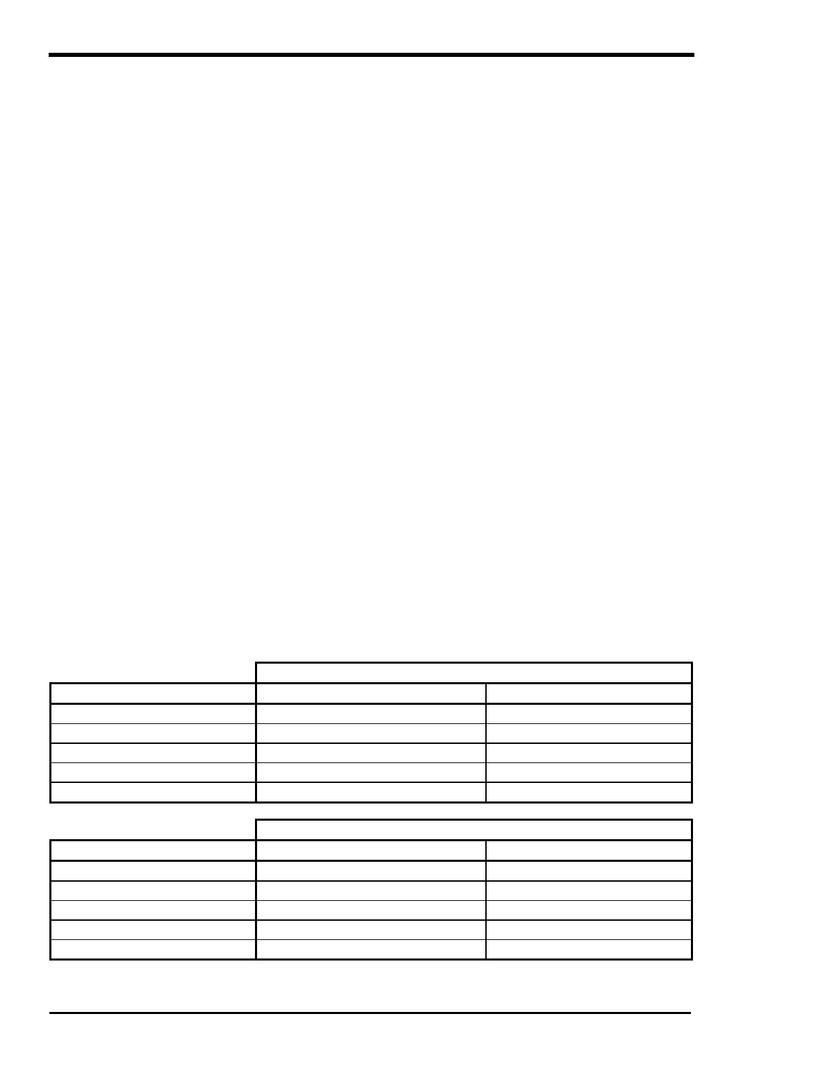
Table 4, AC Input Default Settings
‘MAXIMUM AC AMPS IN’ SWITCH POSITION (120 VAC Models)
INPUT PROVISIONS AC1 AC2
Inverter Lower Limit (VAC) 108 108
Inverter Upper Limit (VAC) 132 132
AC Input Current (AC Amps) 50 30
Frequency (Hz) 53 - 67 (SELL mode = 59 – 61) 53 – 67
Delay Period (seconds) 20 (SELL mode = 90) 60
‘MAXIMUM AC AMPS IN’ SWITCH POSITION (230 VAC Models)
INPUT PROVISIONS AC1 AC2
Inverter Lower Limit (VAC) 206 206
Inverter Upper Limit (VAC) 254 254
AC Input Current (AC Amps) 25 15
Frequency (Hz) 43 – 57 (SELL mode = 49 – 51) 43 – 57
Delay Period (seconds) 20 (SELL mode = 90) 60