OPERATION
Page
80
Copyright Trace Engineering Company, Inc.
5916 - 195th Street N.E.
Arlington, WA 98223
Telephone: 360/435-8826
Fax: 360/435-2229
www.traceengineering.com
PS Series Inverter/Charger
Part No. 3597
Rev. D: November 23, 1999
UTILITY BACK-UP MODE
IN BRIEF
PS Series Inverter/Chargers provide an excellent utility system backup under the majority of powering
applications. Whenever a shorted grid condition affects voltage or frequency, the inverter disconnects
itself from the grid and continues to support the AC load using battery power. Typical transfer time under
a shorted grid condition is instantaneous.
Depending upon the type and amount of load, the transfer may, at times, be noticeable. This is due to the
inverter’s output reaching the overcurrent trip level as it tries to maintain the load before the internal relay
transfers to battery power.
To operate the system in utility back-up mode, set-up the system as follows:
NOTE: All adjustments require the SWRC.
• Connect utility AC power to the inverter's AC HOT IN and AC NEUTRAL IN terminals.
• Connect AC loads to the inverter's AC HOT OUT and AC NEUTRAL OUT terminals.
• Set the ‘MAXIMUM AC AMPS IN’ switch to the AC1 position.
• Adjust the battery charger parameters if the factory default values are not satisfactory. For
applications with small battery banks, lower the battery-charging rate.
• Adjust the GRID (AC1) AMPS AC menu item to match the amperage of the circuit breaker supplying
AC to the inverter input. This setting is located in the AC INPUTS (11) menu heading - (See UTILITY
SUPPORT/OVERLOAD PROTECTION, on page 81).
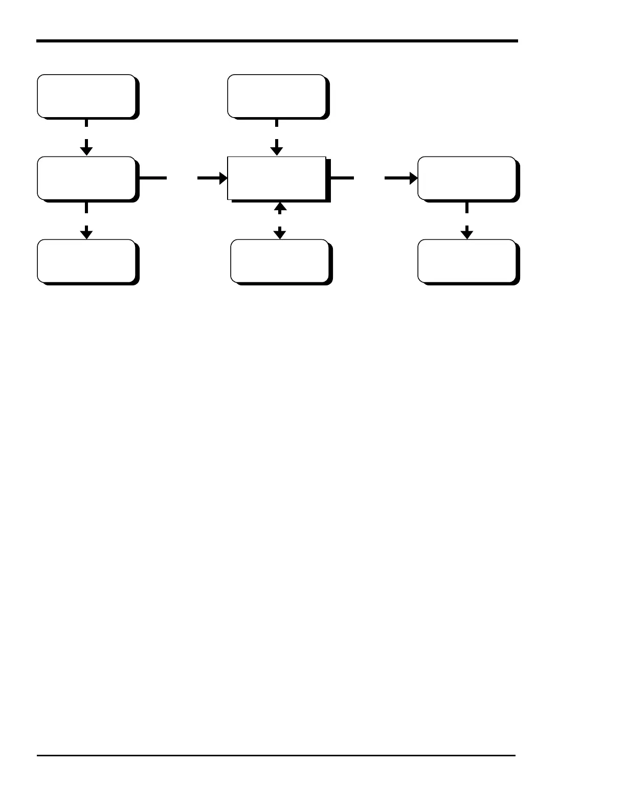
GENERATORUTILITY GRID
AC
INVERTER/
CHARGER
AC BREAKER
PANEL
AC BREAKER
SUB-PANEL
AC AC
BATTERY
NON-CRITICAL
AC LOADS
AC
CRITICAL
AC LOADS
AC
AC
DC