EasyManua.ls Logo

Trace Engineering PS Series User Manual

Trace Engineering PS Series
144 pages
To Next Page IconTo Next Page
To Previous Page IconTo Previous Page
Page #12 background image
CONTROLS, INDICATORS AND COMPONENTS
Page
10
Copyright Trace Engineering Company, Inc.
5916 - 195th Street N.E.
Arlington, WA 98223
Telephone: 360/435-8826
Fax: 360/435-2229
www.traceengineering.com
PS Series Inverter/Charger
Part No. 3597
Rev. D: November 23, 1999
INVERTER/CHARGER CIRCUIT BREAKER
This circuit breaker protects the unit’s internal wiring while the unit is inverting or charging. It is not used
for the pass-through current, which is rated for 50 amps AC. This is not a branch circuit rated breaker,
output breakers are required. Press the breaker to reset.
CIRCUIT BREAKERS
An optional, field installable, Breaker Kit can be ordered which will allow direct hook-up up of up to two
circuits without the use of a separate sub-panel. The Breaker Kit is available with a single 15 or 20 amp
branch circuit rated breaker.
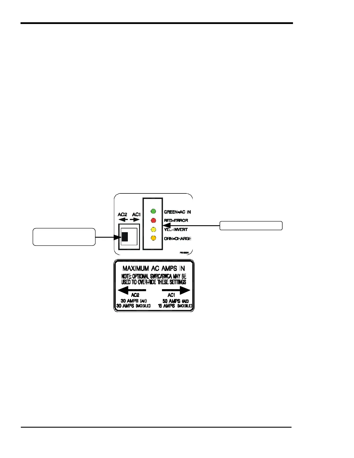
‘MAXIMUM AC AMPS IN’ SWITCH
This switch determines the AC current level at which the inverter begins to back-off the battery charger or
operates in parallel to reduce the load on a generator. This prevents the overloading of the AC source
and prevents nuisance tripping of the AC source circuit breakers. Typically, this is set to the size of the
AC source's (Utility Power or Generator) circuit breaker feeding the inverter or the maximum output
amperage ability of the AC source.
The switch can be switched to the AC1 side to limit the input current to 50 Amps or to the AC2 side to limit
the input current to 30 amps.
The maximum AC input amp size can be adjusted to different settings in the SET GRID (AC1) AMPS AC
and the SET GEN (AC2) AMPS AC menu items using the optional SWRC remote.
Figure 4, ‘Maximum AC Amps In’ Switch And LED Status Indicators
LED STATUS INDICATORS
All PS Series Inverter/Chargers feature four LED status indicators - located on the unit’s front side panel -
that will enable you to monitor the operating mode and system status of your inverter/charger by lighting
one or more of the LED’s. The different colored LED’s will light based on the condition or operating mode
of the inverter/charger. Refer to the LED colors below to determine you unit’s status.
GREEN = AC IN
ON: An AC source has been applied to the AC input terminals of the inverter. When an AC source is
connected to the input terminals the green LED indicator will come on. After a delay period has passed
and once synchronized, the inverter will close an internal relay to connect the AC source to the AC loads
and the inverter will begin to charge the battery and the orange LED indicator will turn solid.
‘Maximum AC Amps In’
switch
LED Status Indicators

Table of Contents

Questions and Answers:

Trace Engineering PS Series Specifications

General IconGeneral
BrandTrace Engineering
ModelPS Series
CategoryInverter
LanguageEnglish

Summary

Important Safety Instructions

General Precautions

General safety guidelines and precautions for using the inverter/charger.

Special Notices

Important notices regarding wiring, tools, and connection requirements.

Personal Precautions

Personal safety measures when working with batteries and the inverter.

Introduction

Controls, Indicators, and Components

Unit Identification

Location and description of model and serial number on the unit's identification label.

On/Off Power Switch

Details on the function and operation of the power switch and its modes.

LED Status Indicators

Explanation of the four LED indicators and their meanings.

‘Maximum AC Amps In’ Switch

Function of the switch for limiting AC input current.

Red = Error LED

Explanation of the red error LED and its conjunction with the yellow LED for mode indication.

Yellow = Invert LED

Detailed explanation of the yellow invert LED status and error conditions.

Error Causes (AC Output Disconnected)

Causes for shutdown that disconnect AC output, like over-current, over-temp, and battery voltage issues.

Error Causes (No AC Output Disconnection)

Advisory error causes that do not disconnect AC output, like input voltage issues or generator faults.

AC Side

AC Circuit Board

Location and components of the AC circuit board, including terminal blocks.

AC Terminal Block

Description of the AC terminal block for hardwiring connections.

AC Ground Terminal

Description of the AC safety ground terminal for chassis connection.

DC Side

Battery Positive & Negative Terminals

Location and connection of battery terminals, with polarity warnings.

Stacking Port

Explanation of the stacking port for connecting multiple inverters.

Remote Port

Description of the remote port for connecting SWRC or SWCA.

DC Equipment/Chassis Ground Terminal

Description of the DC ground terminal for chassis connection.

Installation

Location

Guidelines for selecting an appropriate installation location for the inverter.

Ventilation

Importance of adequate ventilation for efficient operation and preventing thermal shutdown.

AC Wiring

Requirements and recommendations for AC wiring, including connections and codes.

DC Wiring

DC cabling requirements, ampacity ratings, and terminal connections.

Battery Cable Sizing

Guidelines for selecting appropriate battery cable sizes for performance and safety.

DC Disconnect and Overcurrent Protection

Requirements for DC overcurrent protection and disconnect switches.

Battery Cable Connections

Proper methods for connecting battery cables, including polarity and torque.

System Grounding

Comprehensive explanation of system grounding requirements and methods.

Grounding vs. Lightning

Grounding techniques to prevent lightning damage.

One Ground for All Equipment

Importance of a single-point ground system for equipment protection.

Quick Install

DC Cabling

Steps for connecting DC cables to the inverter.

AC In Cabling

Steps for connecting AC input cabling.

AC Out Cabling

Steps for connecting AC output cabling.

Wrap Up

Final checks and securing of wiring.

Functional Test

Step 2: Press the ON/OFF Switch Twice

Testing inverter modes (OFF, SRCH, ON, CHG) and LED indicators.

Step 4: Check Your Battery Charger

Testing the battery charger functionality by providing AC power.

Step 5: Disconnect AC Power

Testing AC power disconnection and inverter transfer.

Menu System

Overview

Explanation of the menu system structure and SWRC/SWCA usage.

SWRC Remote Control

Description of the SWRC remote control's capabilities and functions.

User Menu

Explanation of the USER MENU for daily operations and settings.

Setup Menu

Overview of the SETUP MENU for system configuration and adjustments.

Menu Heading - Inverter Mode (1)

Menu Heading - Generator Mode (2)

Gen Failed to Start

Error cause and reset procedure for generator start failure.

Gen Stopped Due to V/F

Error cause and reset procedure for generator synchronization issues.

Menu Heading - Error Causes (5)

Low Battery Voltage

Condition and action for low battery voltage errors.

Low AC Input Voltage

Condition and action for low AC input voltage errors.

High Battery Voltage

Condition and action for high battery voltage errors.

Gen Failed to Start

Condition and action for generator start failure.

Gen Speed Error

Condition and action for generator frequency adjustment.

Over Current

Cause and resolution for overcurrent conditions.

AC Source Wired to Output

Cause and resolution for AC source wired directly to output.

Menu Heading - Inverter Setup (9)

LBX - Low Battery Transfer Mode

Explanation of the LBX mode for automatic transfer based on battery voltage.

SELL - Sell Mode

Explanation of the SELL mode for selling excess power to the grid.

Menu Heading - Battery Charging (10)

Set Low Battery Cut Out VDC

Setting the voltage level for inverter shutdown due to low battery.

Set Low Battery Cut In VDC

Setting the voltage level for inverter to turn back on after low battery shutdown.

Menu Heading - AC Inputs (11)

Set Input Lower Limit VAC

Setting the minimum acceptable AC input voltage.

Set Input Upper Limit VAC

Setting the maximum acceptable AC input voltage.

Menu Heading - Gen Auto Start Setup (12)

Set Load Start Amps AC

Setting AC load current to initiate generator start.

Set 24 Hr Start Volts DC

Setting battery voltage for 24-hour generator start.

Set 15 Min Start Volts DC

Setting battery voltage for 15-minute generator start.

Menu Heading - Gen Starting Details (13)

Set RY7 Function

Setting the function of Relay 7 for generator start routines.

Menu Heading - Auxiliary Relays R9 R10 R11 (14)

Menu Heading - Low Battery Transfer (LBX) (16)

Set Low Battery Transfer VDC

Setting voltage for transferring loads to utility grid.

Set Low Battery Cut In VDC

Setting voltage for transferring loads back to battery.

Menu Heading - Battery Selling (17)

Set Battery Sell Volts DC

Setting battery voltage level for selling power to grid.

Set Max Sell Amps AC

Setting maximum AC amps for selling power to utility.

Menu Heading - Grid Usage Timer (18)

Operation

Theory of Operation

Explanation of how the PS Series Inverter/Charger works, including its patented design.

Operating Modes

Description of various operating modes like Inverter, Charger, and Utility Interactive.

Inverter Mode

Detailed explanation of the inverter's operation and sine wave approximation.

Low Battery Protection

How the inverter protects the battery from over-discharge.

Charger Mode

Operation of the inverter as a battery charger.

Recommended Battery Charger Settings

Recommended settings for different battery types and chemistries.

Equalizing Charging Batteries

Process and considerations for equalizing batteries.

Inverter/Charger Mode

Automatic transfer of AC loads between inverter and utility/generator.

Generator Support Mode

How the inverter supports the generator by managing loads and battery charging.

Automatic Generator Control Mode

Setting up automatic start/stop control of a backup generator.

Generator Auto Start Requirements and Types

Requirements for generators and types suitable for automatic start.

Utility Back-Up Mode

Providing utility system backup.

Utility Support/Overload Protection

How the inverter supports the utility grid and protects against overloads.

Utility Inter-Active Mode

Using the inverter to move power from DC system to AC utility grid.

Utility Inter-Active Islanding Protection

Protection mechanisms against grid failures and islanding conditions.

Selling Power - Stored in the Batteries

Selling stored battery power to the utility grid.

Sell Mode

Explanation of the SELL mode and its configuration.

Energy Management Modes

Modes for managing utility power usage.

Low Battery Transfer (LBX) Mode

Automatic transfer to utility or stand-alone operation based on battery voltage.

Using Multiple Inverters

Guidelines for using multiple PS Series Inverter/Chargers in a system.

Technical Information

Batteries

Information on battery types, charging, care, and maintenance.

Deep Cycle Battery

Importance of deep cycle batteries for inverter use.

Battery Bank Sizing

Guidelines for determining the required battery bank capacity.

Battery Care and Maintenance

Procedures for proper battery care and maintenance.

Parallel Connection

Connecting batteries in parallel to increase amp-hour capacity.

Series - Parallel Connection

Combining series and parallel connections for voltage and capacity increase.

Battery Cable Inductance

Explanation of battery cable inductance and its impact on performance.

Applications

Discussion of load types (resistive, inductive) and their impact.

Troubleshooting Guide

Guide to diagnosing and resolving issues using LED indicators and SWRC.

Inverter/Charger Terminology

Glossary of terms used in the manual for inverter and battery charger operation.

Specifications and Features

Technical specifications and features of the PS Series Inverter/Charger models.

Dimensions

Physical dimensions of the PS Series Inverter/Charger.

Installation Diagrams

Diagrams to assist with system design and installation.

User Settings Worksheet

Worksheet to record user-specific USER and SETUP operating settings.

Setup Menu (PS2512)

Setup menu items and default settings for PS2512 model.

Setup Menu (PS2524)

Setup menu items and default settings for PS2524 model.

Setup Menu (PS2212E)

Setup menu items and default settings for PS2212E model.

Setup Menu (PS2524E)

Setup menu items and default settings for PS2524E model.

Options

Available options like remote controls and relay modules.

RC8 Remote Control

Description of the RC8 remote control.

GEN Relay Module

Module for generator starting and stopping control.

AUX Relay Module

Module for battery voltage related tasks and AC fault output.

Overcurrent Protection – Fuses and Disconnects

Information on fuse blocks and circuit breaker disconnects.

Warranty/Repair Information

Limited Warranty

Details of the limited warranty and its exclusions.

Warranty Registration

Instructions for registering the product warranty.

Warranty or Repair Service Required

Related product manuals