OPERATION
Page
56
Copyright Trace Engineering Company, Inc.
5916 - 195th Street N.E.
Arlington, WA 98223
Telephone: 360/435-8826
Fax: 360/435-2229
www.traceengineering.com
PS Series Inverter/Charger
Part No. 3597
Rev. D: November 23, 1999
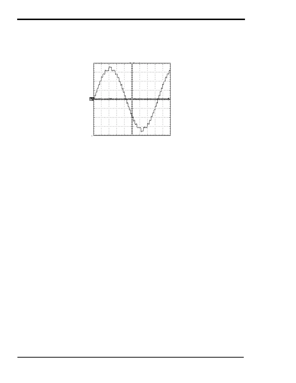
The inverter runs in two basic formats: as a stand-alone inverter (converting DC to AC), or as a parallel
inverter (with its output synchronized to another AC source). In inverter mode, only 60 Hz (50 Hz for
export units) waveforms are created. As the battery voltage rises, waveforms with progressively fewer
steps are generated. More steps are used when battery voltage decreases. Since the battery voltage
tends to drop with increased load, the waveform has increased number of steps with heavier AC loads.
Figure 18, Trace PS Series Inverter/Charger Output Waveform
The inverter is able to synchronize with other AC sources before connecting it to the AC load. The
frequency of the AC source is tracked and the inverter constantly adjusts its frequency to maintain a lock.
A normally open contactor is used to parallel the inverter’s output and the AC source.
The inverter’s power topology is bi-directional. If the waveform created by the inverter has a higher
voltage than the paralleled AC source, then power flows from the batteries to the load. If the waveform
generated has a lower voltage than the AC source, power flows from the source to the battery. The
various modes of operation use different algorithms for determining the size of the waveform to be
created by the inverter. In battery charger mode, for example, waveforms smaller than the AC source are
created to cause current to flow into the batteries. This process is fully regulated to provide a three-stage
charge cycle. If the level of AC current exceeds the user programmed generator or grid size, and then the
inverter will switch to a generator support mode and create waveforms that are larger than the AC source.
This causes power to flow from the batteries to the AC loads to prevent overloading of the AC source.
In utility inter-active mode, the inverter can operate as a battery charger or paralleled AC source to the
utility grid. If an external source such as solar panels attempts to raise the batteries above the float
voltage setting, the inverter will try to hold the battery voltage at the float voltage level by “selling” the
excess power into the utility grid. This is done by increasing the inverter’s output voltage level. This
moves the excess DC power from the solar array to the AC utility grid, preventing the battery from being
overcharged. If the utility grid connected to the inverter is de-energized, the inverter can not regulate the
battery voltage. Some external control device must be provided to prevent damage to the battery.
POWER VS. EFFICIENCY
There are two primary losses that combine to create the efficiency of the PS Series Inverter/Charger. The
first is the energy that is required to operate the inverter at full output voltage while delivering no current.
This is the no load or idle power. At low power levels, the idle power is the largest contributor to efficiency
losses. At high power, the largest source of loss is a result of the resistance in the transformer and power
transistors. The power lost here is proportional to the square of the output power. For Example, losses at
2000 watts will be four times higher than losses at 1000 watts.
The efficiency of a typical inverter is greater while operating resistive loads. Inductive loads such as
motors are run less efficiently due to the impact of power factor losses.