OPERATION
Copyright Trace Engineering Company, Inc.
5916 - 195th Street N.E.
Arlington, WA 98223
Telephone: 360/435-8826
Fax: 360/435-2229
www.traceengineering.com
PS Series Inverter/Charger
Part No. 3597
Rev. D: November 23, 1999
Page
55
OPERATION
The PS Series Inverter/Charger can be configured in many different ways: as a simple stand-alone unit,
working in conjunction with your generator to handle loads too large for the generator alone, allowing
automatic generator start based on battery voltage or loads amp size, or functioning as a utility interactive
inverter which will allow you to send excess power back to the utility grid.
These configurations along with numerous additional features, such as: adjustable charge settings and
automatic battery temperature sensing with the three-stage battery charger; AC/DC voltmeters and AC
ammeters to allow monitoring of inverter, generator, and utility grid; on-board 24-hour clock for
programming of generator quiet time and utility inter-active modes; and an adjustable sellback current
level when using the utility inter-active mode are all available and can be easily accessed using the
SWRC
Often, the inverter will be set-up to operate in several modes at the same or different times - such as
operating as an inverter/charger in utility back-up mode with automatic generator start mode and
generator support mode during extended utility outage periods. The extensive configurations available
are described in the Operating Modes chapter that starts on page 58 and will allow you to enhance and
customize your inverter's particular operation.
Before operating the PS Series Inverter/Charger, ensure that the unit is installed in accordance with the
instructions in the INSTALLATION section beginning on page 17.
THEORY OF OPERATION
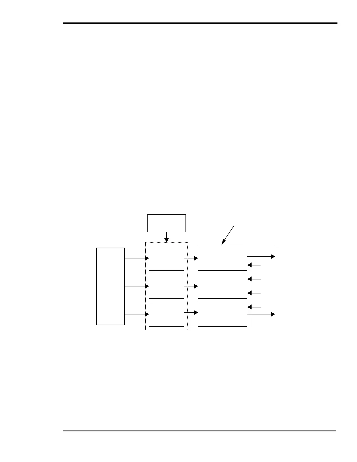
The PS Series Inverter/Charger employs a new patented inverter design. This design uses a combination
of three transformers, each with its own low frequency switcher, coupled in series and driven by separate
interconnected micro-controllers. In essence, it is three inverters linked together by their transformers.
Figure 17, Trace PS Series Inverter/Charger Simple Block Diagram
By mixing the outputs from the different transformers, a sine wave is produced. Shown in Figure 18, is the
output waveform from a Trace Engineering Power Station (PS Series) inverter. Notice the “steps” form a
staircase that is shaped like a sine wave. The total harmonic distortion in this sinewave approach is
typically 3-5%. The multi-stepped output is formed by modulation of the voltage through mixing of the
transformers in a specific order. Anywhere from 34-52 “steps” per AC cycle may be present in the
waveform. The heavier the load or lower DC input voltage the more steps there are in the waveform.
This type of inverter solves many of the problems associated with high frequency or ferro-resonant sine
wave inverters. The low frequency method described has excellent surge ability, high efficiency (typically
85 to 90%), good voltage and frequency regulation, and low total harmonic distortion.
AC
Loads
Battery
Low
Frequency
H-Bridge
Low
Frequency
H-Bridge
Transformer
Transformer
Transformer
Low
Frequency
H-Bridge
Bridges are “mixed” by
Micro-Controllers
Controlling the H-Bridges.
Controllers