CONTROLS, INDICATORS AND COMPONENTS
Copyright Trace Engineering Company, Inc.
5916 - 195th Street N.E.
Arlington, WA 98223
Telephone: 360/435-8826
Fax: 360/435-2229
www.traceengineering.com
PS Series Inverter/Charger
Part No. 3597
Rev. D: November 23, 1999
Page
15
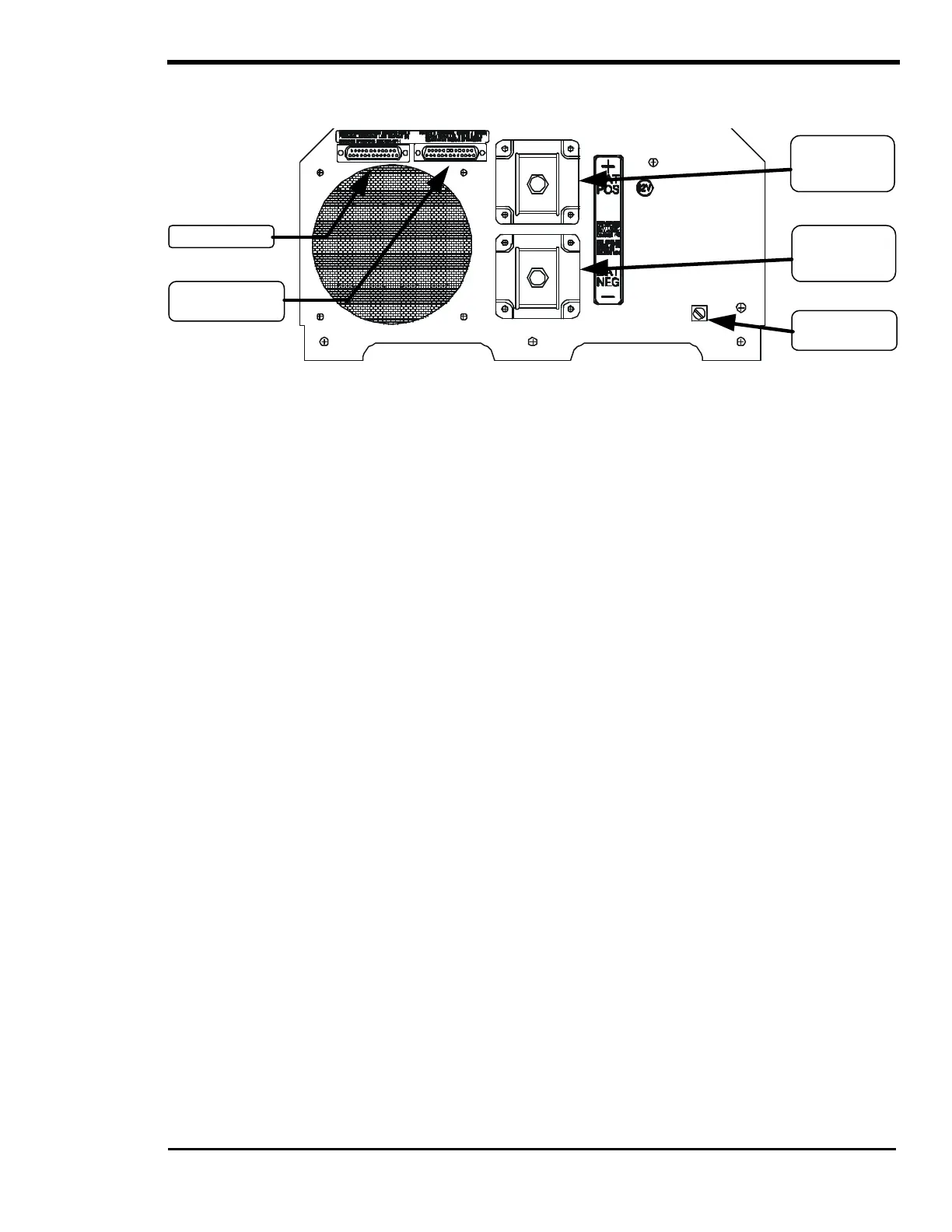
DC SIDE
Figure 9, PS Series DC Side
STACKING PORT
The stacking port allows two PS Series Inverter/Chargers (AE configuration models only) to be used in
the same system. The inverters can be used in a “SERIES” configuration to operate 240 VAC loads and
to connect to 120/240 VAC power systems. A series stacking interface cable (SWI) is required to connect
the series stacking ports of the inverters. This port is also used to connect two units in a “PARALLEL”
configuration. The parallel stacking interface cable (SWI/PAR) allows two inverters to be connected to
provide twice the continuous and surge capability at the same AC voltage. See the USING MULTIPLE
INVERTERS section on page 92 for more information.
REMOTE PORT
The PS Series can be controlled remotely from the unit by plugging in a SWRC remote control or SWCA
communications adapter. See the OPTIONS section starting on page 127 for a complete description of
the SWRC and SWCA.
BATTERY POSITIVE & NEGATIVE TERMINALS
These terminals are where you connect your battery cables. WARNING: Ensure your battery/cable
polarity is correct, this inverter is not reverse polarity protected. If the positive terminal of the battery
is connected to the negative terminal of the inverter and vice versa, the result will be instantaneous failure
of nearly every power transistors. Color-code the cables with colored tape or heat shrink tubing [the
standard is red for positive (+) and black for negative (-)] and double-check the polarity with a voltmeter
before making the battery connections.
DC EQUIPMENT/CHASSIS GROUND TERMINAL
This connection is used to connect the exposed chassis of the inverter to the DC grounding system. The
terminal accepts wires from #14 AWG to #2 AWG.
Battery Cable
Hook-Up
Battery Cable
Hook-Up
Connection
Stacking Port
SWRC or SWCA