INSTALLATION
Page
18
Copyright Trace Engineering Company, Inc.
5916 - 195th Street N.E.
Arlington, WA 98223
Telephone: 360/435-8826
Fax: 360/435-2229
www.traceengineering.com
PS Series Inverter/Charger
Part No. 3597
Rev. D: November 23, 1999
This inverter can create RFI (Radio Frequency Interference). Keep this in mind when determining the
placement of the inverter. You should locate the inverter as far away as possible from any electronic
devices that may be susceptible to RFI.
MOUNTING
UL Standard 1741 requires that the inverter be mounted on a vertical surface (on a wall) and that the
keyhole slots not be used as the only method of mounting. The purpose of the wall mounting requirement
is to orient the inverter so that its bottom cover, which has no holes, will not allow burning material to be
ejected in case of an internal fire. Use 1/4” minimum diameter bolts for mounting. The mounting must be
capable of supporting twice the weight of the inverter in order to comply with UL 1741.
VENTILATION
Installation of the inverter in a properly ventilated area/enclosure is necessary for efficient operation of the
unit. The inverter’s thermal shutdown point will be reached sooner than normal in a poorly ventilated
environment and will result in a lower peak power output, reduced surge capability, and potentially shorter
inverter life. Note: Do not operate the inverter in a closed-in area or restrict ventilation in any way.
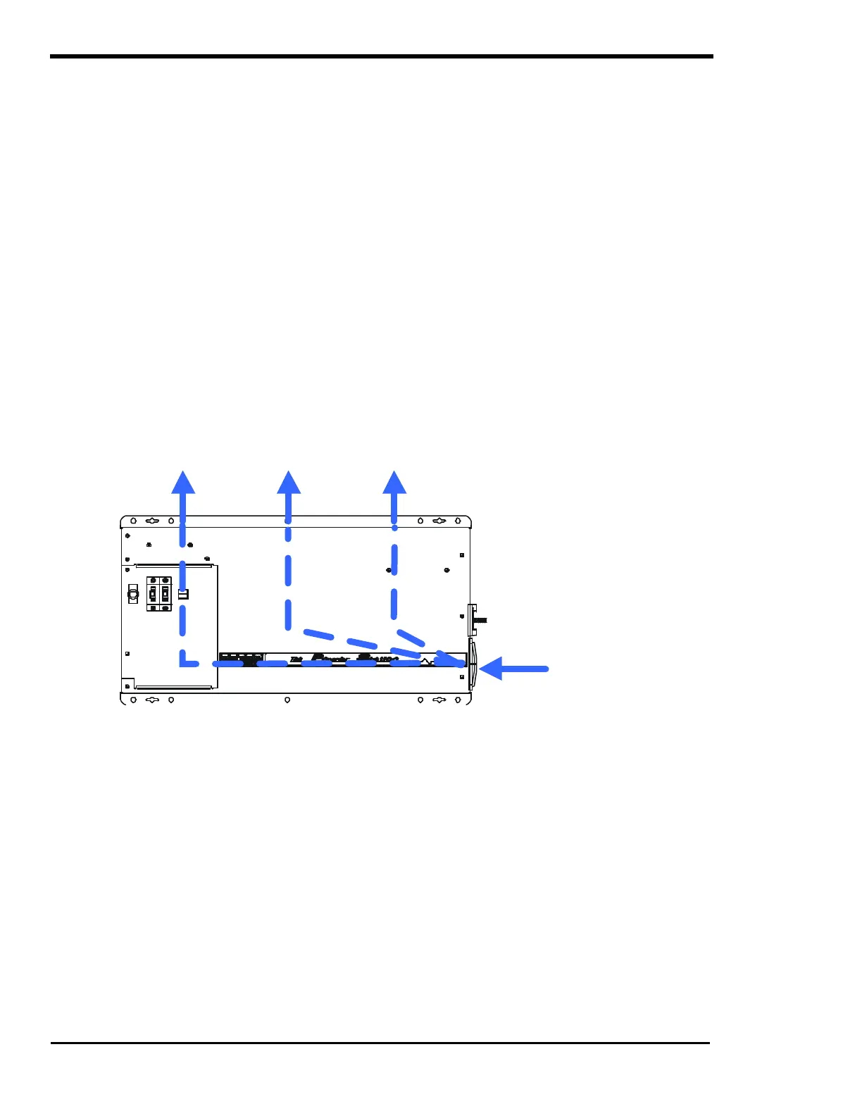
Testing has shown that the volume of the area/enclosure is not as important as the overall ventilation. A
minimum airspace clearance of 1-½ inches around the top and 3 inches of clearance at the right side of
the inverter will provide adequate ventilation. Because the bottom of the PS Series chassis is not vented,
clearance between the enclosure and the bottom of the inverter is not critical. A fresh air intake port
should be provided directly to the right side and an exhaust port on the top side will allow cool outside air
to flow through the inverter and back out of the enclosure.
Figure 10, Airflow Intake Location
AC WIRING
This section describes AC wiring requirements and recommendations; including AC connections; wire
sizing; overcurrent devices; GFCI’s; external relays; hookup procedure; and neutral-to-ground switching.
Your local electrical code and the National Electrical Code (NEC) define the standards for AC installation
wiring, but there are still many installation variables to be considered. Consult the local code and the NEC
for the proper wire sizes, connectors and conduit. All installations should meet all local codes and
standards and be performed by qualified personnel such as a licensed electrician.
AC WIRE CONNECTIONS
IMPORTANT PRECAUTIONS - The AC OUTPUT of the inverter must at no time be connected
directly to utility power or a generator. This condition can be far worse than a short circuit. If the
inverter survives this condition, it will shut down until corrections are made.
A five position terminal block is provided to make the AC connections. The terminal block is located on
the left-hand side of the inverter, enclosed under an access panel (see page 9 for exact location). The
terminal block is used to hardwire all AC connections.
AIR FLOW