MENU SYSTEM
Copyright Trace Engineering Company, Inc.
5916 - 195th Street N.E.
Arlington, WA 98223
Telephone: 360/435-8826
Fax: 360/435-2229
www.traceengineering.com
PS Series Inverter/Charger
Part No. 3597
Rev. D: November 23, 1999
Page
35
USER MENU
This section requires the use of the SWRC (or SWCA). The information in this section is based on
using the SWRC. In this section, whenever the SWRC is mentioned, the SWCA may be used instead.
The USER MENU provides all the controls and settings needed on a daily basis. It allows you to turn on
the inverter and generator, read the AC and DC meters, check on an error cause and even adjust the
inverter’s time clock.
The MENU HEADING buttons are used to move either up or down through the selection of menu
headings. Once a menu heading is selected, the MENU ITEM buttons are used to move up or down
through the list of related menu items. The SET POINTS buttons change the value of a parameter or
select a mode. Two additional buttons are dedicated for automatically selecting two commonly used
menu items. These are ON/OFF MENU and GEN MENU buttons.
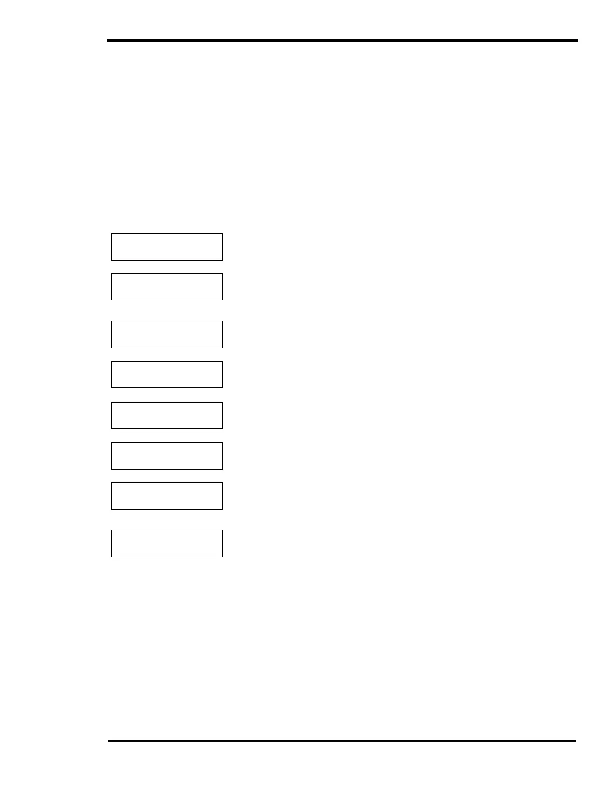
MENU HEADINGS
Inverter Mode
1
Allows control of the inverter and enables the search and charger only
modes.
Generator Mode
2
Allows control of the generator
, enables automatic operation or triggers an
equalization charge cycle. This menu heading is used only if a generator is
included and controlled by the inverter.
Trace
Engineering 3
Provides information for accessing Trace Engineering. Also provides the
software revision number and allows resetting to the factory default values.
Meters
4
Allows monitoring of the DC battery voltage, AC voltages and AC current of
the inverter and other AC sources.
Error Causes
5
Provides an indication of the cause of an error condition. Check this menu
heading if the red ERROR LED indicator is illuminated on the SWRC.
Time of Day
6
Sets the internal 24-hour clock. This is used for time sensitive operating
modes and to determine the “quiet time” period for generator run lockout.
Generator Timer
7
Used to set a run lockout period called “quiet time”. During quiet time, the
generator starts only if the battery voltage reaches the LBCO 30 SEC
START VDC setting.
END USER MENU
8
Used to display that you have reached the end of the USER MENU.